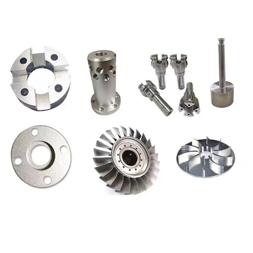
Machining of shafts, rods and spindles
Shafts, rods, and spindles are core components in mechanical transmission systems, playing a vital role in transmitting motion and power. Their machining quality directly impacts the precision, performance, and service life of mechanical equipment. Due to their varying structural characteristics and operational requirements, machining techniques vary. However, all must adhere to the fundamental principles of “rough to fine, exterior to interior, and benchmarking first.” High-quality production is achieved through the rational selection of machining methods, optimized process parameters, and strict precision control.
The machining process for shaft parts focuses on ensuring cylindricity, coaxiality, and surface roughness. Shaft parts typically have a stepped structure with features such as external diameters, shoulders, and keyways. The typical machining process is: forging the blank → normalizing → rough turning → quenching and tempering → semi-finishing turning → finish turning → surface treatment (such as quenching and chrome plating) → grinding → inspection. The rough turning stage removes most machining allowances, using high cutting speeds (100-150 m/min) and high feed rates (0.3-0.5 mm/r) to machine the blank to near-finished dimensions, with a focus on ensuring coaxiality of all external diameters. Quenching and tempering improve the material’s overall mechanical properties, maintaining a hardness of 220-250 HB. Semi-finishing and finish turning gradually improve dimensional accuracy and surface quality. After finish turning, the external diameter can achieve tolerances of IT6-IT7, with a surface roughness of Ra1.6-3.2 μm. For shaft journals requiring higher precision, grinding is required. After grinding, dimensional tolerances can reach IT5, with a surface roughness of Ra0.4-0.8μm. The roundness error of the journal is also guaranteed to be no more than 0.001mm. Machining of auxiliary structures such as keyways is generally performed after semi-finishing and before finishing, using slotting or milling. Keyway symmetry error is controlled within 0.03mm.
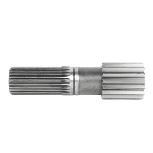
The machining of rod parts, especially slender rods, requires a focused approach to addressing deformation. Slender rods have an aspect ratio greater than 20, resulting in poor rigidity. They are susceptible to bending deformation during machining due to cutting forces, gravity, and thermal stresses. Therefore, the machining process requires the addition of straightening and aging steps: blank rolling → straightening → rough turning → aging → semi-finish turning → straightening → finish turning → grinding → inspection. During rough turning, use a steady rest or steady rest to minimize workpiece deformation. Select low cutting speeds (80-120 m/min) and feed rates (0.1-0.2 mm/r) to avoid excessive cutting forces. Aging eliminates residual stresses and reduces subsequent deformation. For materials such as 45 steel, the aging temperature is 550-600°C, followed by a 2-3 hour hold and slow cooling. During semi-finish turning and finish turning, use a reverse feed method to subject the workpiece to tensile forces rather than bending forces. Use an emulsion with good cooling properties (8%-10%) to reduce cutting temperatures. A centerless grinder or cylindrical grinder is used for grinding, the grinding wheel grit size is 80#-120#, and the grinding depth is controlled at 0.01-0.03mm to ensure that the straightness error of rod parts does not exceed 0.02mm/m.
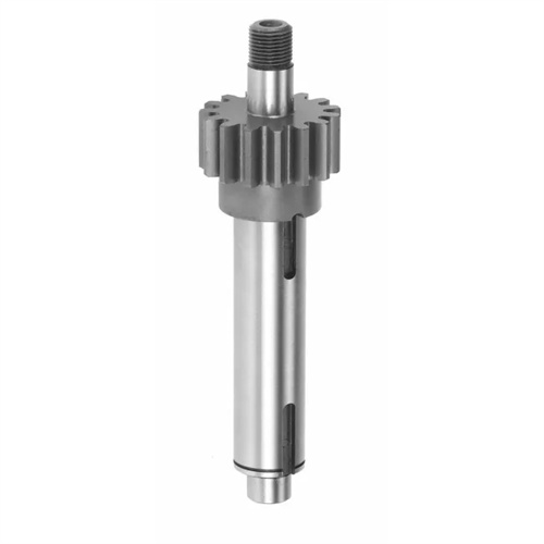
Spindle parts are the most complex to machine, as they must meet high speed, high precision, and high load-bearing requirements. Spindle components typically feature complex structures such as tapered bores, shoulders, threads, and flanges. The machining process follows: blank forging (using alloy structural steel such as 40CrNiMoA) → annealing → rough turning → quenching and tempering → semi-finish turning → surface quenching (spindle journal and taper bore) → rough grinding → aging → fine grinding → super-finishing → inspection. During the rough turning and semi-finish turning stages, strict control of the external diameter and end face precision is required to lay the foundation for subsequent machining. After semi-finish turning, the spindle journal’s dimensional tolerance is controlled to IT8, with a surface roughness of Ra 3.2μm. Surface quenching increases the hardness of the spindle journal and taper bore (HRC 50-55) and enhances wear resistance. After quenching, low-temperature tempering (180-200°C) is required to eliminate quenching stresses. Precision is gradually improved during the rough and fine grinding stages. After fine grinding, the spindle journal’s dimensional tolerance can reach IT5, with a roundness error of no more than 0.0005mm and a taper error of ±5′. Superfinishing further reduces surface roughness to Ra0.025-0.05μm, improving spindle rotational accuracy. Furthermore, thread machining on the spindle is performed before quenching to avoid machining difficulties caused by excessive hardness after quenching. Thread accuracy is maintained at 6g.
The selection of process equipment in the machining of shafts, rods and spindles has a significant impact on quality. When machining the outer circle of shaft parts, a three-jaw self-centering chuck or a four-jaw single-action chuck is used for clamping. The three-jaw chuck is suitable for batch production, and the four-jaw chuck is suitable for single-piece small-batch production and requires alignment. When machining slender rods, a tool rest or center rest must be used. The support jaws of the tool rest must fit well with the outer circle of the workpiece, and the clearance must be controlled at 0.05-0.1mm. If necessary, lubricant should be added between the support jaws and the workpiece. Special fixtures are required for spindle machining, such as spindle taper hole machining fixtures, flange end face machining fixtures, etc., to ensure the positional accuracy between the surfaces. For example, the coaxiality error between the main shaft neck and the taper hole does not exceed 0.002mm. In terms of tool selection, carbide turning tools (such as YT15) are used for rough turning, high-speed steel turning tools (such as W18Cr4V) or coated carbide turning tools are used for fine turning, and white corundum grinding wheels (WA) or silicon carbide grinding wheels (GC) are used for grinding. The appropriate grinding wheel grit and hardness are selected according to the material and precision requirements.
The machining process for shafts, rods, and spindles made of different materials requires specific adjustments. For medium-carbon steels like 45 steel, heat treatment primarily focuses on quenching and tempering, resulting in good machining performance and suitable cutting parameters. For carburizing steels like 20CrMnTi, carburizing (carburized layer depth 0.8-1.2mm) is required after rough turning, followed by quenching and tempering to achieve a surface hardness of HRC 58-62. Carbide tools (such as YW2) should be used during machining, and cutting speeds should be reduced to minimize tool wear. For stainless steels (such as 1Cr18Ni9Ti), due to their high toughness and poor thermal conductivity, work hardening is likely to occur. Therefore, tools with a larger rake angle should be used, with cutting speeds of 80-100 m/min and feeds of 0.1-0.15 mm/r. Extreme-pressure cutting oil should be used for cooling. Cast iron spindles (such as HT300) are brittle and wear-resistant, so YG carbide tools are used for machining at a cutting speed of 100-150 m/min. Dry cutting or kerosene as a cutting fluid can be used to reduce chip adhesion. The machining quality of shafts, rods, and spindles can be guaranteed by optimizing the process based on the material’s characteristics.