Machining of cast iron forks
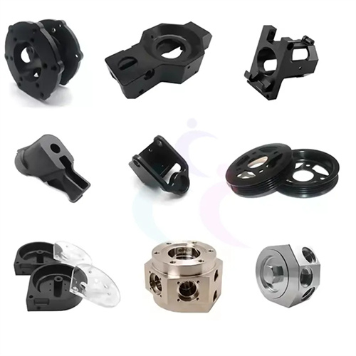
Cast iron shift forks are crucial components in mechanical transmission systems, primarily used to shift gears within transmission mechanisms. They are characterized by complex structure, uneven force distribution, and moderate precision requirements. Gray cast iron (such as HT200 and HT300) is commonly used because of its excellent casting properties, wear resistance, and shock absorption, making it suitable for these complex components. The turning process of cast iron shift forks requires careful consideration of their structural characteristics (including features such as the fork head, fork legs, and shaft hole), a rational machining sequence, and the selection of appropriate tools and cutting parameters to ensure both quality and efficiency.
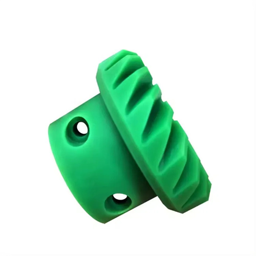
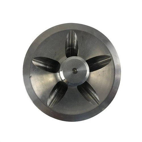
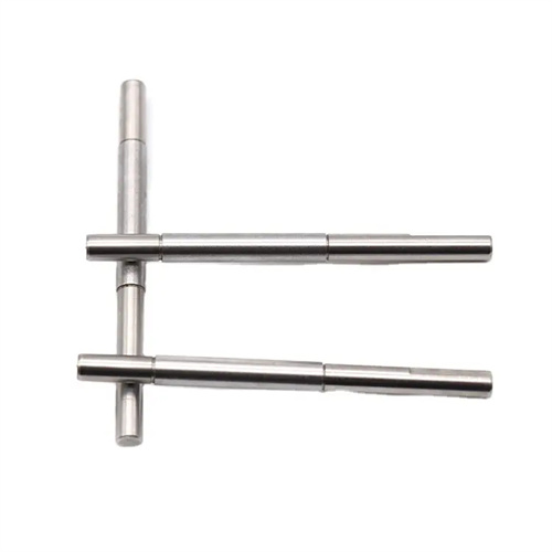
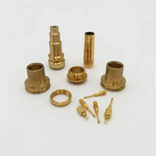
Structural analysis of the cast iron shift fork is fundamental to developing a turning process. A typical cast iron shift fork consists of a fork head, fork leg, and connecting shaft. The fork head has a shaft hole (for mating with the shift shaft), the fork leg has a fork opening (for shifting gears), and the connecting shaft connects the fork head and leg. The overall irregular shape results in poor rigidity, making it susceptible to vibration and deformation during the turning process. The shaft hole, the primary mating surface of the shift fork, typically has dimensional tolerances of IT7-IT8 and a surface roughness of Ra1.6-3.2μm. Its perpendicularity to the connecting shaft must not exceed 0.03mm/100mm. The fork leg width tolerance is ±0.1mm, and the parallelism between the two legs is controlled within 0.05mm to ensure a good fit with the gear fork slot. The connecting shaft has lower requirements for external diameter accuracy; dimensional tolerances of IT9-IT10 and a surface roughness of Ra6.3μm are sufficient. Due to the asymmetric structure of the cast iron fork, it is necessary to reasonably select the positioning reference and clamping method during turning to avoid deformation caused by improper clamping.
The turning process for cast iron shift forks follows the principle of “surfacing first, then drilling, roughing first, then finishing.” The general process is as follows: blank inspection → rough turning of the fork head end face and outer diameter → rough turning of the connecting shaft outer diameter → rough turning of the fork leg end face → drilling the shaft hole → expanding the hole → reaming → finish turning of the fork head end face → finish turning of the shaft hole → turning of the shift fork leg fork mouth → inspection. As the blank is a casting, it must first be inspected to remove the sprue and flash, and inspected for defects such as pores and pinholes. Any defects in critical areas should be repaired. During the rough turning phase, most machining allowances are removed, and high cutting parameters (cutting speed 100-150 m/min, feed rate 0.2-0.4 mm/r, depth of cut 2-4 mm) are used to quickly machine all surfaces to near-finished dimensions, with a focus on ensuring perpendicularity between the fork head end face and the connecting shaft. When drilling, reaming, and ream- ing shaft holes, first drill a base hole (1-2mm smaller than the finished size), then reame to near-finished size, and finally ream to the required accuracy. Reaming uses a machine reamer with a feed of 0.5-1mm/r and a cutting speed of 5-10m/min to ensure dimensional accuracy and surface quality. During the finish turning phase, use lower cutting parameters (cutting speed 150-200m/min, feed 0.1-0.2mm/r, depth of cut 0.5-1mm) to improve the accuracy of all surfaces. After finish turning, ensure that the symmetry error between the shaft hole and the fork leg does not exceed 0.05mm.
The clamping method for turning cast iron shift forks requires careful selection based on the machining stage to ensure accurate positioning and reliable clamping. When rough turning the shift fork head and connecting shaft, a four-jaw single-action chuck can be used. Align the connecting shaft’s outer diameter and the shift fork head’s end face so that the positioning datum coincides with the lathe spindle axis. After alignment, check radial and face runout with a dial indicator, maintaining an error within 0.1mm. During clamping, place copper pads between the jaws and the workpiece to prevent surface damage. When machining the shift fork legs, due to the workpiece’s poor rigidity, a dedicated fixture is required. The fixture uses the fork head’s shaft hole and end face as the positioning datum. Bolts and a pressure plate secure the workpiece to ensure accurate machining of the shift fork legs. The fixture’s positioning error should not exceed 0.03mm. For mass production of cast iron shift forks, pneumatic or hydraulic clamps can be used for automated clamping, improving clamping efficiency and consistency. This can reduce clamping time to 3-5 seconds per piece, significantly improving production efficiency.
The tool selection for turning cast iron forks must be tailored to the material’s characteristics. Gray cast iron has a medium hardness (HB180-240) and is relatively brittle, resulting in chip-crushing. Therefore, the tool must possess high wear and impact resistance. Commonly used tool materials are YG-type carbides (such as YG8 and YG6). YG alloys have a low affinity for cast iron, offer excellent wear resistance, and are less susceptible to adhesive wear. Geometric parameters for rough turning tools include: a rake angle of 5°-10° (avoid excessive rake angles, which can lead to insufficient edge strength), a clearance angle of 8°-12°, a lead angle of 45°-60°, an inclination angle of -5°-0° (to facilitate chip breaking), and a nose radius of 0.5-1mm. For finishing turning tools, rake angles of 10°-15°, clearance angles of 10°-15°, and a lead angle of 75°-90° are recommended to reduce cutting forces and vibration. The tool nose radius is 0.2-0.5mm to ensure surface roughness requirements. The drill bit for processing the shaft hole is a high-speed steel twist drill (such as W18Cr4V), and the reamer is a carbide reamer or a high-speed steel reamer. The reamer has a front angle of 0°-5°, a back angle of 6°-8°, and a blade width of 0.1-0.2mm to ensure the reaming accuracy.
When turning cast iron forks, cutting parameters and cooling and lubrication must be properly controlled. During rough turning, the cutting speed is selected based on the tool material. For gray cast iron using a YG8 carbide turning tool, a cutting speed of 100-180 m/min, a feed of 0.2-0.5 mm/r, and a depth of cut of 2-5 mm is recommended. This achieves high cutting efficiency and moderate tool wear. During finish turning, the cutting speed is increased to 150-250 m/min, the feed reduced to 0.1-0.2 mm/r, and the depth of cut 0.5-1 mm to ensure surface quality. When drilling shaft holes, the drill speed is selected based on the hole diameter. For a drill with a diameter of 10-20 mm, the speed is 800-1200 r/min, with a feed of 0.1-0.2 mm/r. When reaming, the speed is lower (300-500 r/min), with a feed of 0.5-1 mm/r, to avoid excessive wear on the reamer due to excessive speed. Cast iron turning can be lubricated by dry cutting or using kerosene as a cutting fluid. Kerosene effectively flushes chips, reduces scratches on the machined surface, and helps improve surface roughness. The cutting fluid flow rate should be controlled at 5-10 L/min and sprayed directly onto the cutting area. For defective cast iron blanks (such as those with pinholes), reduce the feed rate during turning to prevent tool chipping, and replace the tool if necessary.