Vertical turning of inner and outer cones in cast iron
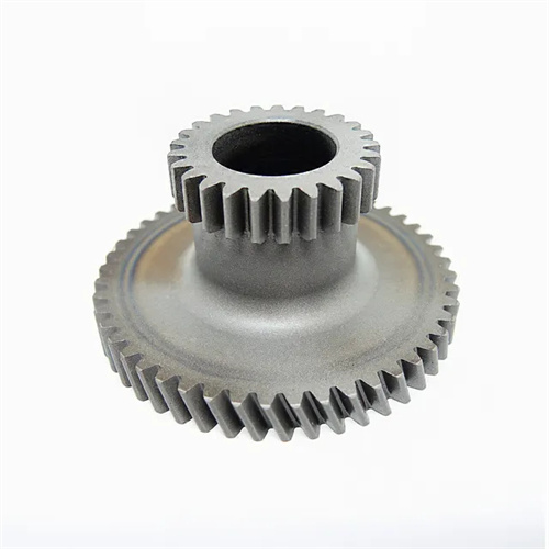
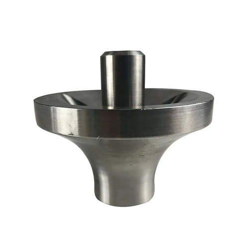
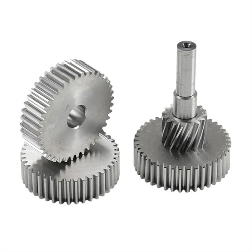
Vertical turning of cast iron internal and external tapers is a process for machining conical surfaces on a vertical lathe. It is suitable for large-diameter, heavy-weight cast iron parts, such as tapered bearing seats and bevel gear blanks for large equipment. With its vertical spindle and horizontal worktable, a vertical lathe can withstand heavy workpiece weights, giving it a unique advantage when machining large cast iron tapers. Compared to horizontal lathes, vertical turning offers greater workpiece clamping stability when machining large-diameter tapers, minimizing the impact of gravity on machining accuracy, thereby ensuring higher taper surface precision.
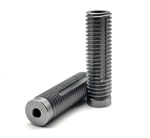
The clamping method for vertical turning of cast iron internal and external tapers must be designed based on the workpiece’s structure and dimensions. The key is to ensure accurate workpiece positioning and secure clamping. For external tapers with large flanges or end faces, the workpiece can be placed directly on the vertical lathe table and clamped using a clamping plate and bolts. The workpiece’s large end face and outer diameter are used as the positioning reference. The radial runout of the outer diameter should not exceed 0.03mm, and the axial runout of the end face should not exceed 0.02mm. For internal tapers, especially thin-walled ones, a dedicated positioning fixture is required. Using the workpiece’s outer diameter or end face as the reference, the fixture’s locating pins mate with the workpiece’s process holes for precise positioning. During clamping, the clamping force must be evenly distributed to prevent workpiece deformation. The clamping force can be controlled with a torque wrench and is typically 20-30N · m . After clamping, the workpiece’s positioning accuracy should be rechecked to ensure it meets machining requirements before turning.
The selection of tools for vertical turning of cast iron conical surfaces requires consideration of the cast iron material’s characteristics and the machining requirements. Cast iron has medium hardness and high brittleness, resulting in chip-crushing. Therefore, tool materials should be YG-type carbides, such as YG8 and YG6, with excellent wear and impact resistance. For machining external tapers, a 45° external turning tool or a dedicated external taper turning tool can be used. The tool’s rake angle should be 5°-10°, and its clearance angle should be 8°-12°. The lead angle is determined by the cone half-angle, generally equal to the cone half-angle plus 5°-10°, to ensure good contact between the tool’s cutting edge and the conical surface. For machining internal tapers, an internal turning tool should be used. The toolholder should have sufficient rigidity to avoid vibration during turning. The tool’s rake angle should be 3°-8°, and its clearance angle should be 10°-15°. The lead angle is also determined by the internal cone half-angle. The grinding quality of the tool has a great influence on the processing accuracy. The cutting edge needs to be sharp and straight. The radius of the tool tip should be selected according to the surface roughness requirements, generally 0.2-0.5mm.
The process parameter settings for vertical turning of internal and external cones in cast iron need to be adjusted in combination with the accuracy requirements of the cone surface and the rigidity of the workpiece. The main task of the rough turning stage is to remove most of the machining allowance. The cutting speed can be selected as 80-120m/min, the feed rate is 0.2-0.4mm/r, and the cutting depth is 2-4mm. Since it is a conical surface, the feeding method can be manual feeding or automatic feeding. When manually feeding, the feed handle needs to be rotated evenly to ensure that the generatrix of the cone surface is straight; when automatically feeding, the rotation angle of the tool holder needs to be adjusted in advance to make it equal to the cone half angle. The accuracy of the cone surface needs to be further improved in the semi-finishing turning stage. The cutting speed is increased to 100-150m/min, the feed rate is reduced to 0.1-0.2mm/r, and the cutting depth is 0.5-1mm. At this time, a template or angle ruler is needed to check the cone angle. If there is any deviation, the tool holder angle should be adjusted in time. The finishing stage is the key to ensuring the accuracy of the conical surface. The cutting speed is controlled at 120-180m/min, the feed rate is 0.05-0.1mm/r, and the cutting depth is 0.1-0.3mm. The surface roughness of the conical surface after finishing should reach Ra1.6-3.2μm, the cone angle error should not exceed ±10′, and the consistency of the taper should not exceed 0.02mm over the entire length.
In the process of vertical turning the inner and outer cones of cast iron, the measurement and adjustment of the cone surface accuracy is an important step in ensuring the processing quality. Commonly used measuring tools include cone gauges, angle rulers, dial indicators, etc. When measuring the outer cone, an outer cone gauge can be used. The through-end gauge should be able to be smoothly inserted on the cone surface, and the contact area of the fitting surface should not be less than 80%. The stop-end gauge should not be completely inserted. When measuring the inner cone, an inner cone gauge is used. After the through-end gauge is inserted into the inner cone, its step surface should be flush with the end face of the workpiece or within the specified range. The insertion depth of the stop-end gauge should be less than the specified value. For cone surfaces with higher precision requirements, an inclinometer or a three-dimensional coordinate measuring machine is required for measurement. The inclinometer can accurately measure the cone half-angle, and the error can be controlled within ±2′; the three-dimensional coordinate measuring machine can comprehensively measure various parameters of the cone surface, including the cone half-angle, taper, roundness, etc., to provide accurate data for precision adjustment. If the measurement reveals deviations in the cone angle, it can be corrected by fine-tuning the tool holder angle. A trial cut is required after each adjustment until the accuracy requirements are met.