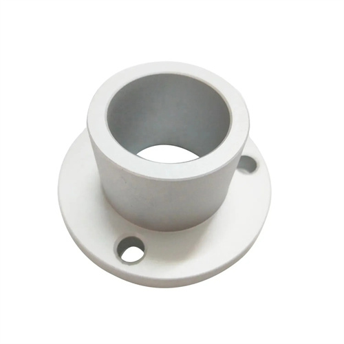
Machining of Carbide Die Taper Sleeve
Carbide mold taper sleeves are key components in the mold industry for positioning, guiding, and force transmission. Due to their high hardness, wear resistance, and dimensional stability, they are widely used in high-precision molds such as stamping and injection molds. Machining carbide mold taper sleeves is challenging, primarily due to the material’s high hardness (typically HRC60-70) and low toughness. This places stringent demands on tool materials, cutting parameters, and machining processes, necessitating a scientifically sound machining plan to achieve high-precision and efficient production.
Tool material selection is a key issue in turning carbide mold taper sleeves, directly impacting machining quality and tool life. Due to the high hardness of carbide, ordinary high-speed steel tools cannot meet cutting requirements, necessitating the use of ultra-hard tool materials. Commonly used tool materials include cubic boron nitride ( CBN ), ceramic tools, and diamond tools. CBN tools offer extremely high hardness ( HV 3000-5000 ) and wear resistance, and can withstand high cutting temperatures ( up to 1200 °C), making them the preferred tool for machining carbide, particularly materials with a hardness of HRC 50 or higher. Ceramic tools (such as Al₂O₃ -based ceramics and Si₃N₄ -based ceramics) have high hardness and excellent chemical stability, but relatively poor toughness. They are suitable for finishing operations with low speeds and small feed rates. Diamond tools have the highest hardness (HV 10000), but due to their chemical affinity for iron group elements, they are not suitable for machining ferrous carbide. They are primarily used for machining non-ferrous carbide (such as tungsten carbide). The geometric parameters of the tool also need to be carefully designed. The rake angle is generally -5°-0° (negative rake angle can increase blade strength), the back angle is 5°-8°, and the main deflection angle is 45°-60° to reduce cutting force and vibration.
The turning process for carbide mold taper sleeves requires a phased approach, including rough turning, semi-finishing, and finishing, to gradually improve machining accuracy. Rough turning aims to remove most of the machining stock. Due to the brittleness of carbide, rough turning requires lower cutting speeds ( 80-120 m/min for CBN tools), smaller feeds (0.05-0.1 mm/r), and depths of cut (0.1-0.3 mm) to avoid excessive cutting forces that could cause workpiece cracking or tool breakage. Climb milling should be used whenever possible during rough turning to minimize tool-workpiece impact. Semi-finishing turning further enhances dimensional accuracy and surface quality. Cutting speeds can be increased to 100-150 m/min, feeds 0.03-0.08 mm/r, and depths of cut 0.05-0.15 mm. After semi-finishing, the surface roughness of the taper surface should achieve a Ra of 3.2 μm or higher, with the taper angle error controlled within ±5°. Finish turning is a key process to ensure the accuracy of the taper sleeve. It requires a higher cutting speed (150-200m/min), smaller feed rate (0.02-0.05mm/r) and cutting depth (0.02-0.05mm). The surface roughness of the tapered surface after finish turning should reach Ra0.8-1.6μm, the taper tolerance should not exceed 0.005mm/100mm, and the large and small end diameter tolerances should be controlled at IT5-IT6 level.
Controlling taper surface accuracy is a key challenge in turning carbide mold taper sleeves, requiring precise machine tool adjustment and measurement. Key parameters of the taper surface include angle, taper, and diameter. The angle can be measured with a universal protractor, sine rule, or angle gauge block. For high-precision taper sleeves, an optical dividing head or a coordinate measuring machine (CMM) is required. The taper angle error should be controlled within ±2′. Taper consistency must be checked along the entire length. This can be achieved using a taper plug or ring gauge. The through end of the plug (or ring) should fit smoothly, while the stop end should not. The contact area of the mating surfaces should be at least 80%. The diameter should be measured at both the large and small ends of the sleeve. A micrometer or internal diameter indicator (for internal sleeves) can be used. Care should be taken to avoid excessive force that could deform the workpiece or gauge. The measurement error should be controlled within 0.002mm. To ensure the accuracy of the tapered surface, the radial runout and axial movement of the lathe spindle must be controlled within 0.003mm, and the sliding plate’s moving straightness must not exceed 0.005mm/100mm.
Cooling, lubrication, and chip evacuation are crucial aspects of turning carbide mold taper sleeves, directly impacting machining quality and tool life. Due to the high temperatures in the cutting zone, a cutting fluid with excellent cooling and lubricating properties is required. For ferrous carbide machining with CBN tools, an extreme pressure emulsion (containing extreme pressure additives such as sulfides and chlorides) can be used. A concentration of 10%-15% and a flow rate of at least 20 L/min should be used. This fluid should be sprayed directly into the cutting zone through a high-pressure nozzle to dissipate the cutting heat. When machining non-ferrous carbide, kerosene or specialized cutting oils can be used to reduce tool-workpiece adhesion. Poor chip evacuation can cause chips to scratch the machined surface and even damage the tool. Therefore, an appropriate chip evacuation device, such as a spiral chip conveyor or high-pressure air blower, is required to ensure timely chip removal. For internal taper sleeve turning in enclosed areas, chip flutes can be incorporated into the tool to guide chips. The width and depth of the flute should be designed based on chip size, typically 3-5 mm wide and 2-3 mm deep.
The clamping method for carbide mold taper sleeves must be designed based on their structure and dimensions, with the key focus being on ensuring accurate positioning and secure clamping. For external taper sleeves, either a three-jaw self-centering chuck or a four-jaw single-action chuck can be used. Three-jaw chucks are suitable for mass production and offer quick clamping, but they offer lower centering accuracy (0.01-0.03mm). Four-jaw chucks are suitable for small-batch production of single pieces and can achieve higher centering accuracy (0.005-0.01mm) through alignment. During clamping, copper padding should be placed between the workpiece and the jaws to prevent surface damage. For internal taper sleeves with steps or flanges, a faceplate clamping system can be used. A pressure plate presses the workpiece against the faceplate, ensuring alignment of the outer diameter and end faces to within 0.005mm. For thin-walled taper sleeves (less than 5mm thick), specialized fixtures or soft jaws are required to minimize clamping deformation. The clamping force should be evenly distributed, and a torque wrench can be used to control the clamping force to avoid plastic deformation of the workpiece. Before clamping, the positioning reference surface of the workpiece needs to be cleaned to remove burrs and oil stains, and ensure that the positioning surface fits tightly with the fixture, with the fitting gap not exceeding 0.002mm.