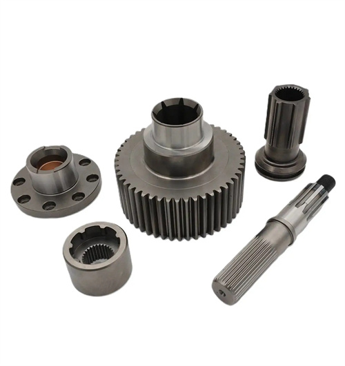
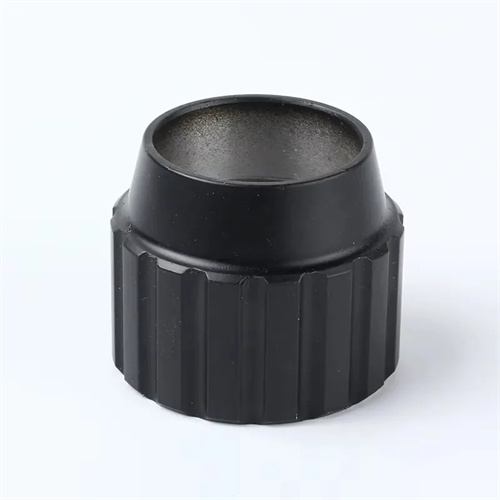
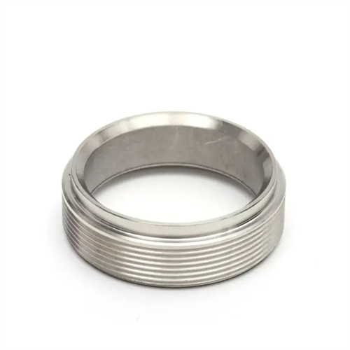
Machining of Tin Bronze Trapezoidal Screw Nuts
Tin bronze trapezoidal lead screw nuts are key components for achieving helical motion in mechanical transmissions. Due to their excellent wear resistance, friction reduction, and anti-adhesion properties, tin bronze is widely used in precision transmission systems. The quality of their turning directly impacts the screw-nut fit and transmission efficiency. Therefore, a scientific and rational turning process must be developed based on the material properties of tin bronze and the structural characteristics of the trapezoidal thread.
Machining tin-bronze trapezoidal lead screw nuts first requires addressing the challenges posed by the material’s processing properties. Tin bronze (such as ZCuSn10P1) has medium strength and low hardness (approximately HB80-100), but exhibits good plasticity. This makes it susceptible to tool sticking during turning, resulting in defects such as galling and scratching on the thread surface. Furthermore, tin bronze has excellent thermal conductivity, allowing cutting heat to be easily dissipated by the workpiece and chips. This reduces tool overheating during high-speed cutting. However, plastic deformation of the material can also generate high cutting forces, exacerbating tool wear. To address these issues, appropriate tool material must be selected before turning. YG-type cemented carbide (such as YG6 and YG8) is generally preferred. These tools offer high wear resistance and anti-sticking properties, effectively reducing tool sticking. Tool geometry should include a large rake angle (12°-18°) and clearance angle (6°-10°) to reduce cutting forces and friction. The rake face should be finely ground to a surface roughness of Ra 0.8μm or less to prevent chip sticking.
The turning process of trapezoidal internal threads is a core step in the machining of tin-bronze nuts, requiring a phased approach of rough turning, semi-finishing, and finishing. Rough turning primarily aims to remove the majority of the machining stock, utilizing a low cutting speed (60-100 m/min), a high feed rate (0.3-0.5 mm/r), and a depth of cut (1-2 mm). Internal thread turning tools with a 90° lead angle can be used, employing a straight-cut method to minimize tool-workpiece contact. Semi-finishing turning requires adjusting cutting parameters, increasing the cutting speed to 80-120 m/min, reducing the feed rate to 0.15-0.25 mm/r, and controlling the depth of cut to 0.3-0.5 mm. A left-right cutting method can be employed, with slight adjustments to the center slide feed rate to cut from both sides of the thread, to avoid deformation caused by excessive force on one side. Finish turning is the key to ensuring thread accuracy. The cutting speed needs to be further increased to 100-150m/min, the feed rate should be controlled at 0.08-0.15mm/r, the cutting depth should not exceed 0.15mm, the tool tip arc radius of the finish turning tool should be smaller than the thread bottom fillet, and a constant speed cutting mode should be used to ensure that the thread surface roughness reaches Ra1.6μm or above.
Controlling the dimensional accuracy of internal threads is a difficult point in turning tin-bronze nuts, and this requires precise measurement and process adjustments. The main parameters of trapezoidal threads include major diameter, minor diameter, mean diameter, pitch, and thread angle. The accuracy of the mean diameter directly affects the fit clearance between the screw and the nut. During measurement, a trapezoidal thread plug gauge can be used for comprehensive inspection. The through end of the plug gauge should be able to be screwed into the nut smoothly, and the stop end must not be screwed in. For high-precision nuts, the mean diameter must be measured using the three-needle measurement method. Before measurement, the chips and oil in the thread groove must be cleaned, and the measuring force must be controlled at 5-10N to avoid dimensional deviations caused by excessive measuring force. If the mean diameter is found to be out of tolerance during measurement, the back cutting amount during fine turning must be adjusted. For every 0.01mm adjustment in the back cutting amount, the mean diameter will change by approximately 0.014mm (the specific value needs to be corrected according to the thread lead angle). The control of pitch error needs to be achieved by adjusting the transmission ratio of the lathe screw and the spindle. Before turning, the lathe needs to be tested for dry running to ensure that the axial runout of the screw does not exceed 0.01mm/100mm and the radial runout does not exceed 0.005mm.
The clamping method of tin-bronze nuts significantly affects machining accuracy, and the appropriate clamping solution must be selected based on the nut’s structure and size. For thin-walled nuts (less than 10mm thick), direct clamping with a three-jaw self-centering chuck can easily cause clamping deformation, resulting in excessive thread cross-section ovality. In this case, soft jaws should be used. The jaws should be customized to the nut’s outer diameter. Copper pads should be placed in the clamping area to minimize damage to the workpiece surface. The clamping force should be controlled at 20-30kN. After clamping, the clamping force should be maintained for 5-10 minutes to release the stress before turning. For nuts with flanges, a faceplate clamping system can be used. The flange end face is pressed against the faceplate surface using a pressure plate. The outer diameter runout should be aligned to no more than 0.02mm, and the end face runout should be no more than 0.01mm, ensuring the coaxiality of the thread axis with the positioning datum. During clamping, the nut axis should be prevented from deviating from the lathe spindle axis. Otherwise, the thread profile half angle will be asymmetrical, affecting the meshing quality with the lead screw.
The appropriate choice of cutting fluid can effectively improve the turning performance of tin-bronze nuts, enhancing machining quality and tool life. Because tin-bronze tends to stick to the tool, the cutting fluid needs to possess excellent lubricity and cooling properties. Extreme-pressure emulsions (8%-12% oil content) are typically used. Extreme-pressure additives (such as sulfurized lard and chlorinated compounds) can form a chemical adsorption film on the tool surface, reducing chip adhesion. The cutting fluid should be supplied with high-pressure internal cooling, spraying the fluid directly onto the cutting area at a controlled flow rate of 15-20 L/min and a pressure of 0.3-0.5 MPa to ensure prompt removal of chips and avoid secondary cutting. For finish turning, sulfurized cutting oil can be used, as it offers superior lubrication and can effectively reduce thread surface roughness. However, caution should be exercised regarding the corrosive nature of sulfurized oil on copper. After machining, the nuts should be cleaned immediately with kerosene and coated with rust-inhibiting oil. Furthermore, the cutting fluid should be filtered regularly to remove copper chips and impurities, maintain cleanliness, and prevent scratching of the machined surface.