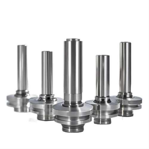
Machining of step sleeve
A step sleeve is a sleeve-like component with multiple steps of varying diameters. It is widely used in machinery manufacturing, automobiles, machine tools, and other fields, primarily for positioning, supporting, and connecting components such as bearing sleeves, gear sleeves, and hydraulic cylinder sleeves. The structure of a step sleeve is characterized by multiple steps on the outer circle or inner hole, with strict dimensional and geometric tolerances (such as coaxiality, perpendicularity, and step length tolerance) between each step. The difficulty in turning a step sleeve lies in ensuring the dimensional accuracy, geometric tolerances, and perpendicularity of each step end face. Therefore, it is necessary to rationally design the machining process and select the appropriate clamping method, tool, and cutting parameters.
The material selection for step sleeves should be determined based on operating conditions and performance requirements. Commonly used materials include 45 steel, 20 steel, 40Cr, and HT250. 45 steel is suitable for step sleeves under normal loads. After quenching and tempering, it reaches a hardness of 220-250 HB and exhibits excellent overall mechanical properties. 20 steel is suitable for step sleeves requiring carburizing and quenching, achieving a surface hardness of 58-62 HRC and excellent core toughness. 40Cr is suitable for step sleeves subjected to heavy loads, achieving high strength and toughness after quenching and tempering. HT250 gray cast iron is suitable for step sleeves under low speeds and light loads, offering excellent wear resistance and vibration damping. The blank type is selected based on production batch size and size. Small and medium-sized step sleeves are made from round steel. Large-sized step sleeves or those produced in large batches are made from forgings or castings to improve material utilization and mechanical properties. The machining allowance of the blank needs to be determined according to the accuracy requirements of the step sleeve. Generally, a machining allowance of 3-5mm is reserved for the outer circle and inner hole, and a machining allowance of 1-2mm is reserved for the step end face.
The machining process for step sleeves should follow the principle of “roughing to finishing, from large to small,” meaning the large-diameter step should be machined first, followed by the small-diameter step; roughing, semi-finishing, and finally finishing. The typical process is: blanking → forging/casting → annealing → rough turning of the outer diameter, end faces, and inner bore → quenching and tempering → semi-finishing turning of the outer diameter, end faces, and inner bore (leaving allowance) → finish turning of the outer step → finish turning of the inner step → final inspection. The primary task of the rough turning stage is to remove most of the allowance and maintain the basic shape of each surface. After rough turning, a 1-2mm semi-finishing allowance is reserved for the outer diameter and inner bore, and a 0.5-1mm allowance is reserved for the step end faces. Quenching and tempering improves the material’s cutting and mechanical properties. For 45 steel step sleeves, tempering (840°C water quenching followed by 550°C tempering) results in a hardness of 220-250HB, making them suitable for subsequent finishing. In the semi-finishing turning stage, the shape error after rough turning needs to be corrected to ensure that the dimensional accuracy of each step basically meets the requirements, and a finishing allowance of 0.1-0.3mm is reserved.
The clamping method for the step sleeve should be selected according to its structure and size to ensure processing accuracy and rigidity. For small and medium-sized step sleeves, a three-jaw self-centering chuck can be used for clamping. This is convenient and efficient, making it suitable for mass production. However, attention should be paid to correcting the coaxiality of the workpiece, and radial runout should be ≤0.02mm. For slender step sleeves with an aspect ratio greater than 5, a one-clamp-one-top clamping method should be adopted, that is, one end is clamped with a three-jaw chuck and the other end is supported by a top, which increases the rigidity of the workpiece and reduces processing deformation. For large-sized step sleeves or step sleeves with high precision requirements, a four-jaw single-action chuck is used for clamping. Alignment is performed to ensure that the workpiece axis coincides with the spindle axis, and the alignment accuracy can reach 0.005mm. During clamping, attention should be paid to the clamping force to avoid workpiece deformation. For thin-walled step sleeves, soft jaws or open sleeves can be used to clamp to reduce clamping deformation.
The tool selection for turning step sleeves should be determined based on the surface and material properties. Commonly used tools for turning external steps include 90° external turning tools, 45° turning tools, and grooving tools. 90° external turning tools are suitable for turning the outer diameter and end face of the step, ensuring perpendicularity between the end face and the outer diameter; 45° turning tools are suitable for turning chamfers and end faces; grooving tools are used to turn the grooves between the steps, with the width determined by design requirements. Commonly used tools for turning internal steps include through-hole boring tools, blind-hole boring tools, and internal groove tools. Through-hole boring tools are suitable for turning through-hole steps; blind-hole boring tools are suitable for turning blind-hole steps, and attention should be paid to the tool shank length and rigidity; internal groove tools are used for turning internal grooves. Tool Material Selection: Use carbide tools such as YT15 and YT5 for steel machining; YG6 and YG8 for cast iron machining; and W18Cr4V high-speed steel or coated carbide tools for finishing to improve surface quality. Tool Geometry: External turning tools have a rake angle of 10°-15°, a clearance angle of 6°-8°, and a lead angle of 90°. Boring tools have a rake angle of 5°-10°, a clearance angle of 8°-10°, and a lead angle of 75°-90°.
The cutting parameters and precision control of the step sleeve must be determined according to the machining stage and precision requirements. For rough turning, to improve efficiency, the cutting speed is 80-100 m/min, the feed rate is 0.2-0.3 mm/r, and the cutting depth is 2-3 mm. For semi-finishing turning, the cutting speed is 100-120 m/min , the feed rate is 0.15-0.2 mm/r, and the cutting depth is 0.5-1 mm. For finishing turning, the cutting speed is 120-150 m/min, the feed rate is 0.1-0.15 mm/r, and the cutting depth is 0.1-0.3 mm. Cutting fluid selection: Use extreme pressure emulsion for steel machining; use kerosene or emulsion for cast iron machining. In terms of precision control, the step length tolerance is generally controlled within ±0.05-±0.1mm, which can be controlled by the lathe’s longitudinal feed scale or digital display device; the dimensional tolerance of the step outer circle and inner hole is generally controlled at IT7-IT8 level, measured with a micrometer or internal diameter dial indicator; the coaxiality error is controlled within 0.01-0.03mm, which can be ensured by machining the outer circle and inner hole in one clamping; the verticality error of the step end face is controlled within 0.01-0.02mm/100mm, measured with a dial indicator. For example, when turning a bearing step sleeve, the outer diameter of the step is φ80mm and φ60mm respectively, with a tolerance of h6 (-0.