Processing technology of eccentric sleeve
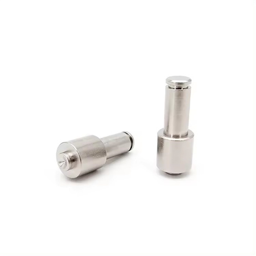
An eccentric sleeve is a sleeve-like part whose axis is parallel to, but not overlapping, a reference axis. It is widely used in the transmission mechanisms of machine tools, engines, textile machinery, and other equipment, achieving reciprocating or intermittent motion through an eccentric structure, such as the eccentric journal of a crankshaft or the eccentric wheel of a cam mechanism. The main parameters of an eccentric sleeve include the eccentricity (the distance between the two axes), the inner and outer diameters, and length of the eccentric sleeve, as well as geometric tolerances such as coaxiality and perpendicularity between the eccentric portion and the reference portion. The difficulty in machining an eccentric sleeve lies in ensuring the accuracy of the eccentricity and the geometric tolerances of the eccentric portion, while also controlling deformation of the part. Therefore, it is necessary to rationally design the machining process and select appropriate clamping methods, machining methods, and measuring tools.
The material selection and blank preparation for eccentric sleeves must be determined based on the operating conditions. Common materials include 45 steel, 40Cr, and 20CrMnTi. 45 steel is suitable for eccentric sleeves subjected to normal loads. After quenching and tempering, it reaches a hardness of 220-250HB and exhibits excellent overall mechanical properties. 40Cr is suitable for eccentric sleeves subjected to medium loads. After quenching and tempering, it reaches a hardness of 240-280HB, with high strength and toughness. 20CrMnTi is suitable for eccentric sleeves subjected to impact loads. After carburizing and quenching, it reaches a surface hardness of 58-62HRC and a core hardness of 30-40HRC, exhibiting high wear resistance and impact toughness. The blank type is selected based on the production batch size. For small-batch production, round steel blanks are used; for large-scale production, die forgings are used to improve material utilization and mechanical properties. The dimensional tolerance of the blank needs to be determined according to the machining allowance. Generally, a machining allowance of 5-8mm is reserved for the outer diameter and length, and a machining allowance of 3-5mm is reserved for the inner diameter. The straightness error of the blank should be ≤0.5mm/m to avoid affecting the subsequent machining accuracy.
The machining process for eccentric sleeves must adhere to the principle of “benchmarking first, then machining in stages.” A typical process is: blanking → forging → annealing → rough turning the outer diameter, end face, and inner bore → quenching and tempering → semi-finishing the outer diameter and end face → marking the eccentricity line → drilling the bottom hole in the eccentric portion → rough turning the eccentric outer diameter → aging → semi-finishing the eccentric outer diameter and inner bore → finish turning the outer diameter and end face → finish turning the eccentric outer diameter and inner bore → final inspection. The primary task of the rough turning stage is to remove the majority of the excess stock, laying the foundation for subsequent machining. After rough turning, a 2-3mm semi-finishing allowance is reserved for the outer diameter and inner bore, and a 1-2mm allowance is reserved for the end face. Quenching and tempering (840°C water quenching followed by 550°C tempering for 45 steel) improves the material’s machinability and mechanical properties, reducing subsequent machining distortion. When semi-finishing the reference outer circle and end face, the accuracy of the reference surface must be guaranteed. The roundness of the reference outer circle is ≤0.02mm, and the perpendicularity between the end face and the reference axis is ≤0.01mm/100mm, providing a reliable positioning reference for the processing of the eccentric part.
The clamping method of the eccentric sleeve is the key to ensuring the accuracy of the eccentricity. The commonly used clamping methods are as follows: For eccentric sleeves with small eccentricity (e≤5mm), a three-jaw self-centering chuck and shim can be used. A shim with a thickness of x is padded on one of the jaws of the chuck, where x≈1.5e (e is the eccentricity). The thickness of the shim is adjusted by trial cutting to ensure that the eccentricity error is ≤0.01mm; for eccentric sleeves with large eccentricity (e>5mm), a four-jaw single-action chuck is used for alignment, and a dial indicator is used to measure the runout of the eccentric outer circle. The position of the jaws is adjusted to make the eccentricity meet the requirements, and the alignment accuracy can reach 0.005mm; for eccentric sleeves produced in batches, a special eccentric fixture is used, which is equipped with a locating pin and an eccentric sleeve. The locating pin cooperates with the reference hole of the workpiece to ensure the consistency of the eccentricity, high production efficiency, and an eccentricity error ≤0.02mm . When clamping, attention should be paid to the rigidity of the workpiece. For slender eccentric sleeves with a length-to-diameter ratio greater than 5, a center stand or tool rest should be used for support to avoid bending deformation during processing.
The turning of the eccentric sleeve should be performed in stages, gradually improving accuracy. For rough turning of the eccentric outer diameter, a YT15 carbide turning tool should be used, with a cutting speed of 80-100 m/min, a feed rate of 0.2-0.3 mm/r, a cutting depth of 2-3 mm, and a semi-finishing allowance of 0.5-1 mm. During semi-finishing, eccentricity and roundness errors must be corrected. A trial cut can be used to measure the dimensions of the eccentric outer diameter and the eccentricity, adjust the tool position, and allow a finishing allowance of 0.1-0.3 mm after semi-finishing. For finishing, a W18Cr4V high-speed steel turning tool or a TiAlN-coated carbide turning tool should be used, with a cutting speed of 60-80 m/min, a feed rate of 0.1-0.15 mm/r, and a cutting depth of 0.1-0.2 mm. Emulsion cooling should be used to ensure a surface roughness Ra ≤ 1.6 μm. When finishing the inner hole, use a floating boring tool or reamer to ensure the dimensional accuracy and roundness of the inner hole. The coaxiality error between the inner hole and the eccentric outer circle should be ≤0.02mm. For eccentric sleeves with auxiliary structures such as keyways and pin holes, they need to be processed after finishing to avoid stress generated during machining of the auxiliary structures that affects the accuracy of the eccentric sleeve.
The accuracy inspection of eccentric sleeves requires parameters such as dimensional accuracy, form and position tolerances, and eccentricity. Dimensional accuracy inspection uses a micrometer to measure the diameters of the outer circle and inner hole, with tolerances generally controlled to IT7-IT8. Form and position tolerance inspection uses a dial indicator and V-block to measure the roundness (≤0.01mm), cylindricity (≤0.015mm), and coaxiality (≤0.02mm) of the eccentric outer circle. Eccentricity is measured using a dial indicator or eccentricometer. The dial indicator method places the eccentric sleeve’s reference outer circle on a V-block and rotates the workpiece. The eccentricity is determined by half the difference between the maximum and minimum readings on the dial indicator, with a measurement accuracy of up to 0.005mm. The eccentricometer method offers even higher accuracy, reaching 0.001mm, and is suitable for inspecting high-precision eccentric sleeves. For mass-produced eccentric sleeves, first-piece inspection and sampling inspection are required. Mass production can only be carried out after the first-piece inspection is qualified. The sampling ratio is generally 5%-10% to ensure the stability of product quality.