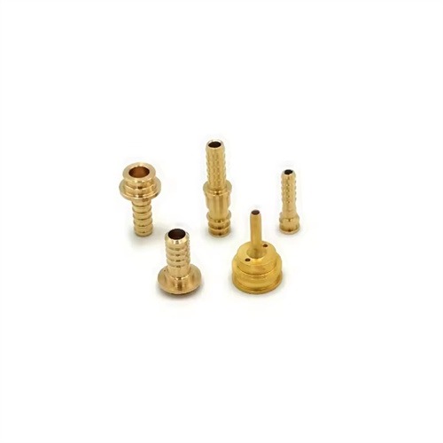
Machining of alloy steel double eccentric shaft
Alloy steel double-eccentric shafts are complex precision components featuring two eccentric sections with different axes. They are widely used in transmission mechanisms in automotive engines, precision machine tools, aerospace, and other fields, playing a vital role in transmitting motion and power. Due to their use of alloy steel (such as 40CrNiMo and 20CrMnTi) and their double-eccentric structure, turning them presents challenges such as difficult clamping, high centrifugal forces, and challenging precision control. The high strength and toughness of alloy steel further increase cutting resistance and the tendency toward work hardening. Therefore, a targeted machining plan is required, requiring comprehensive optimization of clamping methods, tool selection, cutting parameters, and process routes to ensure part dimensional accuracy, form and position tolerances, and surface quality.
The reasonable selection of clamping method is the primary difficulty in turning alloy steel double eccentric shafts, which directly affects the stability of the machining process and the eccentricity accuracy. The two eccentric sections of the double eccentric shaft usually have an angular difference (such as 90°, 180°, etc.), and precise positioning is required to ensure the relative position accuracy. For small and medium-sized double eccentric shafts, a double-pin clamping method with an eccentric clamp can be used: a process center hole is machined at both ends of the shaft, and the workpiece is fixed between the spindle and the tailstock by an eccentric clamp. The locating pins on the clamp cooperate with the locating holes on the workpiece to ensure the accuracy of the eccentric direction. This method has high positioning accuracy and can ensure that the angular tolerance of the two eccentric sections is ≤±15′, but attention should be paid to the machining accuracy of the process center hole, and its coaxiality error should be controlled within 0.01mm. For large double-eccentric shafts, a four-jaw single-action chuck combined with a steady rest can be used. Use a dial indicator to align the first eccentric segment. After machining, release the chuck, rotate the workpiece to a preset angle, and then realign the second eccentric segment. Alignment accuracy must reach 0.01mm/100mm. Regardless of the clamping method used, the centrifugal force on the workpiece must be balanced. Vibration can be reduced by adding balancing blocks or adjusting the cutting speed to avoid compromising machining accuracy and surface quality.
The choice of tool material and geometry must be tailored to the cutting characteristics of the alloy steel. For example, when machining alloy steel double-eccentric shafts, 40CrNiMo, with a hardness of 28-32 HRC, generates high cutting forces and temperatures. Therefore, the tool must possess both high strength and wear resistance. YG8 carbide tools are recommended for roughing, as they contain a high cobalt content (8%) and offer a bending strength of 1800 MPa, capable of withstanding significant impact loads. For semi-finishing and finishing, YT15 or TiAlN-coated carbide tools are recommended. YT15 offers excellent wear and heat resistance, making it suitable for continuous cutting. TiAlN-coated tools, with a surface hardness exceeding 3000 HV and a low coefficient of friction, effectively reduce work hardening and tool sticking. Tool geometry requires targeted design: a rake angle of 5°-10° to minimize cutting deformation; a clearance angle of 8°-12° to reduce flank friction; a lead angle of 75°-90° to reduce radial cutting forces and prevent workpiece bending; and a nose radius of 0.4-0.8mm to enhance tip strength while minimizing surface residual area. For machining eccentric steps, a forming tool must be used to ensure perpendicularity between the step end face and the axis. The perpendicularity error should be ≤0.01mm/m.
Optimizing cutting parameters requires a balance between machining efficiency and quality to avoid vibration or work hardening caused by inappropriate parameters. For roughing, a YG8 tool turning 40CrNiMo should maintain a cutting speed of 60-80 m/min; for finishing, a YT15 tool should maintain a speed of 100-120 m/min, and TiAlN-coated tools can increase this to 120-150 m/min. Higher speeds reduce tool-workpiece contact time and reduce work hardening. Feed rates should be adjusted according to the machining stage: 0.2-0.3 mm/r for roughing to quickly remove stock; 0.1-0.15 mm/r for semi-finishing; and 0.08-0.1 mm/r for finishing to ensure a surface roughness Ra ≤ 1.6 μm. The depth of cut should be reduced in a stepwise manner: 2-3 mm for the first roughing operation, decreasing by 0.5-1 mm each time, leaving a 0.1-0.2 mm allowance for the final finishing operation. Because centrifugal force increases with speed when the dual eccentric shaft rotates, the cutting speed should be appropriately reduced when the eccentricity exceeds 5mm. If necessary, low-speed cutting (30-50m/min) should be adopted, and the toolholder should be used to enhance rigidity to prevent radial runout of the workpiece. Runout should be controlled within 0.02mm. The cutting fluid should be an extreme pressure emulsion with a concentration of 10%-15%. It should be injected directly into the cutting zone through high-pressure spray (pressure of 2-3MPa) to reduce temperature and improve lubrication.
The machining process must adhere to the principle of “benchmarking first, then machining in stages” to ensure gradual improvement in the precision of the double eccentric shaft. A typical process is: blanking → forging → annealing → rough turning of the outer diameter and end faces → quenching and tempering → semi-finishing turning of the base shaft segment → finish turning of the first eccentric segment → rough turning of the second eccentric segment → semi-finishing turning of the second eccentric segment → aging → finish turning of the second eccentric segment → final inspection. The quenching and tempering treatment (850°C oil quenching + 550°C tempering) uniformizes the hardness of the 40CrNiMo steel to 28-32 HRC and eliminates forging stresses. The aging treatment (180°C for 4 hours) eliminates residual stresses after semi-finishing and prevents deformation during final finish turning. The machining order of the two eccentric segments depends on the required angle. If 180° symmetry is required, the first eccentric segment should be machined first, then the workpiece should be rotated 180° before machining the second segment. If the angle is 90°, an indexing device should be used for accurate positioning. During machining, a dial indicator is used to monitor the eccentricity in real time. The clamping position is adjusted to maintain an eccentricity tolerance within ±0.01mm. After final finishing, the coaxiality of the two eccentric segments (relative to the reference axis) is checked. The error should be ≤0.02mm, and the angular tolerance between the eccentric segment axes should be ≤±10° to ensure that assembly requirements are met.