Machining of steel three-ball handle
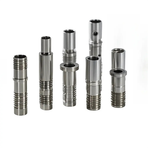
A steel three-ball handle is a rod-shaped component with three spherical ends. It is commonly used in machine tool operation, valve control, and tool holding. Its structural feature is a rod connected to three symmetrically spaced spheres. The spheres must be perfectly round, have a smooth surface, and be securely connected to the rod. Due to the complex shape of the spheres and the right-angle or obtuse transition with the rod, the turning process must ensure the geometric accuracy, positional precision, and surface quality of the spheres, while avoiding stress concentration at the transition point. The turning of a steel three-ball handle requires careful consideration of its structural characteristics, with the appropriate selection of machining methods, tools, and process parameters to achieve efficient and high-quality production.
The blank selection and pretreatment for steel three-ball handles significantly impact subsequent turning operations. Common materials include 45 steel and 40Cr. For more demanding applications, 2Cr13 stainless steel can be used to improve corrosion and wear resistance. The blank is typically round steel bar stock. The diameter is determined by the maximum diameter of the ball, generally 3-5mm larger than the diameter. The length is determined by the total handle length plus a machining allowance. Blank pretreatment includes normalizing or annealing. Normalizing 45 steel (holding at 850-880°C followed by air cooling) refines the grain size, homogenizes the microstructure, and controls the hardness to 170-217HB, improving cutting performance. Annealing of alloy structural steels such as 40Cr reduces hardness and prevents work hardening. Blanks with forging defects require flaw detection to ensure the absence of cracks, inclusions, and other defects to prevent chipping during machining. Both ends of the blank must be sawn flat to provide a reference for subsequent clamping and positioning.
Sphere turning is a core step in the machining of steel three-ball handles. Common methods include form-tool turning, guide turning, and CNC turning. Form-tool turning is suitable for mass production. The tool edge is ground to an arc that matches the radius of the sphere. The sphere’s contour is turned in a single pass through the tool feed. While efficient and simple to operate, it requires high tool grinding precision and is therefore suitable for applications where precision is less critical. Guide turning uses a guide device to control the tool’s trajectory. The circular groove on the guide matches the radius of the sphere, and the tool moves with the guide to achieve spherical turning. This ensures a roundness error of ≤0.01mm and a surface roughness of Ra ≤3.2μm, making it suitable for medium-volume production. CNC turning uses a program to program the spherical surface, controlling the tool’s circular interpolation motion. This allows for precise control of the sphere’s size and shape, achieving a roundness of up to 0.005mm and a surface roughness of Ra ≤1.6μm. It is suitable for high-precision, complex-shaped three-ball handles, and is particularly well-suited for single-piece, small-batch production. When turning a sphere, it is necessary to first rough-turn the prototype of the sphere, leaving a 0.5-1mm finishing allowance, and then perform semi-finishing turning and finishing to gradually improve the accuracy.
Special care must be taken when turning the transition between the shank and the sphere to avoid stress concentration and surface defects. This transition is typically rounded or right-angled, with a radius of 1-3mm. A dedicated fillet cutter is required to ensure a smooth transition. During turning, the tool should be fed from the sphere toward the shank to avoid deformation of the sphere due to cutting forces generated when feeding from the shank to the sphere. For right-angle transitions, a 90° offset tool should be used, with multiple passes of 0.1-0.2mm each, ensuring a smooth transition surface perpendicular to the shank axis. The surface roughness of the transition should be controlled to Ra ≤ 3.2μm, avoiding burrs and tool marks. Manual refining should be performed as necessary. For handles with more demanding requirements, the transition can be rolled to improve surface hardness and fatigue strength. Rolling can increase hardness by 10-20HB and improve surface roughness to Ra ≤ 0.8μm.
Tool selection and cutting parameter settings need to be adjusted according to the material and machining stage. When turning carbon steels such as 45 steel, YT15 carbide tools can be used for roughing, and YT30 for finishing to improve surface quality. When machining stainless steel, YG8 or YW2 tools are used to reduce tool sticking and work hardening. For ball turning, the tool rake angle should be 8°-12°, the clearance angle should be 6°-10°, and the cutting edge inclination angle should be -5°-0° to enhance cutting edge strength. For shank turning, the rake angle can be increased to 10°-15° to reduce cutting forces. For rough turning, the cutting speed for 45 steel should be 80-120 m/min, and for stainless steel, 60-100 m/min; for finish turning, increase the speed to 120-180 m/min and 100-150 m/min, respectively. The feed rate for rough turning is 0.2-0.3 mm/r, and for finish turning, 0.08-0.15 mm/r. The cutting depth is 1-3mm for rough turning and 0.1-0.5mm for fine turning. The cutting fluid is an extreme pressure emulsion, and extreme pressure cutting oil can be used for fine turning to improve lubrication and reduce surface scratches.
The clamping and quality control of steel three-ball handles require a design that takes into account their structural characteristics. Due to the symmetrical distribution of the three spheres, the workpiece axis must be aligned with the spindle axis during clamping. For long-stem handles, a one-clamp-one-top clamping method can be adopted, with a live center as the tailstock center to reduce friction and heat generation. When turning the first sphere, the rod can be clamped directly; when turning subsequent spheres, a dedicated fixture is required to position them and ensure that the symmetry of the three spheres does not exceed 0.1mm. During machining, the curvature of the spheres is checked with a radius template, the roundness is measured with a dial indicator, and the diameter of the spheres is measured with a caliper to ensure that the dimensional tolerance is within ±0.1mm. For mass production, special inspection fixtures can be manufactured for comprehensive testing. After machining, burrs must be removed and the surface of the spheres polished to a surface roughness of Ra ≤ 0.8μm, improving both the feel and aesthetics. For handles that require corrosion resistance, surface treatment is also required, such as galvanizing, chrome plating or bluing. The coating thickness is controlled at 5-10μm to ensure uniform plating without missing.