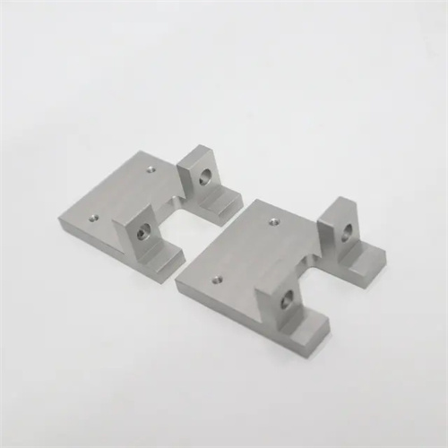
Machining of cast iron porous bracket
Cast iron porous brackets are essential components in mechanical equipment, primarily used to support shafts, bearings, and other components. They feature multiple parallel or perpendicular hole systems, complex structures, and excellent rigidity. Commonly made from gray cast iron (HT250, HT300) or ductile iron (QT400-15), they are widely used in machine tools, automobiles, and construction machinery due to their excellent casting properties, vibration damping, and low cost. The turning process of cast iron porous brackets focuses on ensuring the dimensional and positional accuracy (such as parallelism, perpendicularity, and coaxiality) of each hole, as well as the positional relationship between the hole and the plane. This requires rational process planning and precise machining control.
The structural characteristics of cast iron porous brackets dictate the complexity of their turning process. Porous brackets typically feature one or more mounting surfaces and multiple through-holes or blind holes. The hole axes may be perpendicular or parallel to the planes, and strict positional tolerances are imposed on the holes. For example, a machine tool porous bracket features three through-holes with diameters of φ50mm, φ30mm, and φ20mm, respectively. The perpendicularity error between the φ50mm hole and the mounting surface must not exceed 0.02mm/100mm, the parallelism error between the φ30mm hole and the φ50mm hole must not exceed 0.03mm/100mm, and the hole spacing error must be controlled within ±0.05mm. The mounting surface of the bracket must have a surface roughness of Ra3.2μm and a flatness error of no more than 0.05mm/100mm, serving as a reference for other surface machining. Due to the large number of holes and their complex positional relationships, a reasonable positioning reference and machining sequence must be determined during turning to avoid cumulative errors caused by datum conversion.
The turning process for cast iron porous brackets follows the principle of “benchmark first, staged machining.” The general process is: blank inspection → rough turning of the mounting surface → aging treatment → finish turning of the mounting surface → rough turning of the reference hole → rough turning of other holes → semi-finish turning of each hole → finish turning of each hole → turning of the end face and outer diameter → inspection. The blank, being a casting, undergoes inspection and is machined first, after passing inspection. This serves as a positioning reference for subsequent machining. A facing tool is used for rough turning of the surface at a cutting speed of 100-150 m/min, a feed rate of 0.2-0.4 mm/r, and a depth of cut of 2-4 mm. Surface scale and casting defects are removed, and flatness is maintained within 0.1 mm. Aging treatment eliminates casting stresses and reduces subsequent deformation. For gray cast iron, the aging temperature is 500-550°C, held for 4-6 hours, and then slowly cooled. The installation plane is fine-turned with a carbide end turning tool, with a cutting speed of 150-200m/min, a feed rate of 0.1-0.2mm/r, a cutting depth of 0.5-1mm, and a flatness error of no more than 0.03mm/100mm after fine turning, with a surface roughness of Ra1.6μm.
Machining the reference hole is crucial for turning porous brackets, ensuring dimensional accuracy and perpendicularity to the mounting surface. When rough-turning the reference hole (usually the largest or most critical hole), the final mounting surface is used as the reference for positioning. Using a three-jaw chuck or specialized fixture for clamping, the bottom hole is drilled with a twist drill, followed by an expansion drill. The rough-turned hole size is 1-2mm smaller than the finished product, with a perpendicularity error of 0.05mm/100mm. Boring tools are used for semi-finishing and finish turning of the reference hole. Semi-finishing turning uses a cutting speed of 100-150 m/min, a feed rate of 0.15-0.3 mm/r, and a cutting depth of 0.5-1 mm. Finish turning uses a cutting speed of 150-200 m/min, a feed rate of 0.05-0.15 mm/r, and a cutting depth of 0.1-0.3 mm. Finish turning achieves an IT7 tolerance for the reference hole, a surface roughness of Ra 1.6 μm, and a perpendicularity error of no more than 0.02 mm/100 mm. Other holes are machined using the reference hole and the mounting plane as the positioning reference. Hole positions are determined using the coordinate method or template method. Parameters for roughing, semi-finishing, and finish turning are similar to those for the reference hole to ensure accurate positioning of each hole relative to the reference hole.
The clamping method and tool selection for turning the cast iron porous bracket need to adapt to its structural characteristics. During clamping, the installation plane and the reference hole after fine turning are used as the positioning reference, and the one-side two-pin positioning method is adopted, that is, the installation plane fits the positioning plane of the fixture, and the two positioning pins are inserted into the reference hole and the other auxiliary hole to achieve complete positioning. The positioning error is controlled within 0.02mm. The clamping adopts a bolt pressure plate, which is evenly distributed around the workpiece. The clamping force is moderate to avoid deformation of the workpiece. For thin-walled parts, a support block needs to be placed between the pressure plate and the workpiece to enhance rigidity. In terms of tool selection, the turning surface adopts a hard