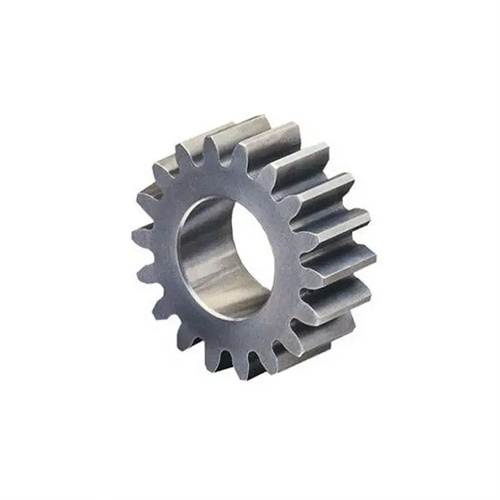
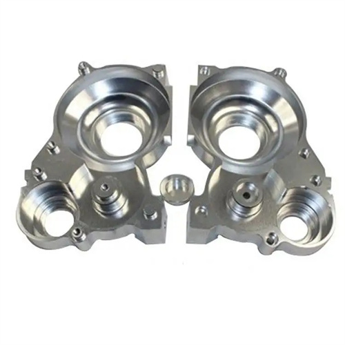
Milling spur gears is a common gear processing method in machining, suitable for gear production with low precision requirements and small batch sizes. Spur gears are widely used in various mechanical transmission systems due to their simple structure, smooth transmission, and convenient machining. The key to milling spur gears lies in ensuring tooth profile accuracy, pitch uniformity, and tooth surface quality. This is achieved through the appropriate selection of milling cutters, adjustment of the indexing mechanism, and optimization of cutting parameters.
The selection of a milling cutter for spur gears depends on the gear’s module, number of teeth, and precision requirements. Spur gears have an involute tooth profile, and gears with different modules and tooth counts require different milling cutters. National standards classify involute gear milling cutters into eight groups, each containing eight (or 15) milling cutters of different sizes, corresponding to different tooth count ranges. For example, a #1 milling cutter is suitable for gears with 12-13 teeth, while a #2 milling cutter is suitable for gears with 14-16 teeth. The larger the size, the wider the tooth count range. When selecting a milling cutter, choose the closest size to the actual number of teeth on the gear to minimize tooth profile error. The module of the milling cutter must match the module of the gear, and the pressure angle is typically 20° (standard pressure angle). In terms of tool materials, when processing low-carbon steel, cast iron and other materials, high-speed steel milling cutters (such as W18Cr4V) can be used, which are suitable for low-speed milling; when processing medium-carbon steel, alloy steel and other materials, carbide milling cutters (such as YT15) should be used to improve cutting speed and processing efficiency.
Adjusting the indexing mechanism is crucial for ensuring uniform pitch on spur gears. When milling gears, after each tooth groove is milled, the indexing mechanism rotates the workpiece a certain angle before milling the next tooth groove. This angle is called the indexing angle, and its value is 360°/z (where z is the number of gear teeth). A commonly used indexing mechanism is a universal indexing head with a transmission ratio of 1:40. This means that for every 40 rotations of the indexing head handle, the workpiece rotates once. Therefore, the number of rotations of the indexing handle, n, equals 40/z. For tooth numbers that are not evenly divisible, an indexing disk is used for indexing. The disk has multiple different hole circles. The appropriate hole circle is selected through calculation so that the number of holes rotated by the indexing handle is (40/z) × the number of hole circles. For example, when milling a 17-tooth gear, n = 40/17 ≈ 2.3529. A 43-hole circle can be selected, and two rotations of the indexing handle add 10 holes (2 × 43 + 10 = 96, 96/43 ≈ 2.2326, close to 2.3529). When adjusting the indexing mechanism, ensure that the indexing head spindle is perpendicular to the worktable, the indexing handle rotates freely without binding, and the indexing error should be within ±5″.
The milling process for spur gears is typically divided into two stages: rough milling and finish milling. The purpose of rough milling is to remove most of the machining allowance, laying the foundation for finish milling. During rough milling, a lower cutting speed (10-20 m/min for high-speed steel milling cutters, 30-50 m/min for carbide milling cutters), a larger feed rate ( 0.1-0.2 mm/r), and a depth of cut (1-2 mm) can be used. During rough milling, the tooth groove depth should be milled to 0.5-1 mm shallower than the designed dimension, leaving an allowance for finish milling. Finish milling, aimed at ensuring gear accuracy and surface quality, requires a higher cutting speed (20-30 m/min for high-speed steel milling cutters, 50-80 m/min for carbide milling cutters), a smaller feed rate (0.05-0.1 mm/r), and a depth of cut (0.3-0.5 mm). During fine milling, the tooth groove depth must be strictly controlled to meet the design requirements. The tooth thickness deviation should be controlled within the range of ±0.015mm, and the tooth surface roughness should reach Ra3.2μm or above.
Measuring tooth profile accuracy and pitch error is an important means of verifying the machining quality of spur gears. Tooth profile accuracy refers to the degree of conformity of the gear tooth profile to the theoretical involute. This measurement can be performed using a profile gauge. For gears with lower precision requirements, comparison with a template is also acceptable. Pitch error includes individual pitch error and cumulative pitch error. Individual pitch error is the difference between the actual and theoretical arc lengths of two adjacent tooth spaces. Cumulative pitch error is the maximum difference between the actual and theoretical arc lengths between any two tooth flanks on the same side of the pitch circle. Pitch error can be measured using a pitch gauge. The gauge is placed on the gear’s pitch circle, and each adjacent pitch is measured sequentially, calculating the error. For grade 8 gears, the individual pitch error should not exceed 0.025mm, and the cumulative pitch error should not exceed 0.05mm. Additionally, gear dimensions such as the addendum diameter, root diameter, and tooth width should be measured to ensure they meet design requirements.
Milling spur gears made of different materials requires different process measures. When machining brittle materials like cast iron, the chips are powdery and easily fly. A protective cover should be installed on the workbench and chips should be cleaned regularly to prevent them from entering the machine tool guideways and affecting precision. Dry cutting or the use of kerosene as a cutting fluid can reduce the risk of dust to humans and the machine tool. When machining plastic materials like 45 steel, the chips are ribbon-like and easily entangled with the milling cutter. A milling cutter with a chip breaker should be used, and an emulsion (8%-10% concentration) should be used as a cutting fluid to cool and lubricate the tool and reduce built-up edge. When machining difficult-to-machine materials like stainless steel, due to their high toughness and poor thermal conductivity, work hardening is likely to occur. Therefore, a carbide milling cutter with high hardness and good wear resistance (such as YW1 or YW2) should be used. A lower cutting speed (10-20 m/min) and a smaller feed rate (0.05-0.1 mm/r) should be used, and the cooling effect of the cutting fluid should be enhanced.