Straightening and clamping of slender shafts
Due to their large aspect ratio and poor rigidity, slender shafts are prone to bending and deformation during processing, heat treatment, and storage, affecting their performance and assembly accuracy. Therefore, straightening and clamping slender shafts are crucial for ensuring machining quality. Straightening aims to eliminate bending and deformation, ensuring that the shaft meets straightness requirements; clamping aims to maintain the correct position of the slender shaft during machining and prevent further deformation. Straightening and clamping slender shafts require appropriate methods and tools based on the degree of deformation and machining requirements.
Straightening methods for slender shafts primarily include manual straightening, press straightening, and flame straightening. The appropriate method should be selected based on the shaft material, diameter, and degree of curvature. Manual straightening is suitable for slender shafts with smaller diameters (generally less than 30mm) and less severe curvature. The shaft is placed between two V-shaped iron bars and the degree and direction of curvature are measured using a dial indicator to determine the point of maximum curvature. Pressure is then applied with a hammer or wrench in the opposite direction of the point of maximum curvature, causing the shaft to deform in the opposite direction to offset the original curvature. Manual straightening requires repeated measurement and tapping until the straightness error of the shaft does not exceed 0.1mm/m. Press straightening is suitable for slender shafts with larger diameters (30-100mm) and more severe curvature. The shaft is placed on the press worktable, with a block placed below the point of maximum curvature. Pressure is applied from above using a press head to induce plastic deformation, achieving the desired straightening effect. During press straightening, the pressure must be controlled to avoid breaking the shaft or causing excessive deformation. The shaft deformation can be monitored in real time using a dial indicator until the desired straightening result is achieved. Flame straightening is suitable for slender shafts made of materials such as alloy structural steel. Flame heats the bent portion of the shaft (typically at 600-800°C), causing localized plastic deformation. After cooling, the shaft bends in the opposite direction of the heating, achieving the desired straightening effect. Flame straightening offers high precision, but the process is complex and requires experienced personnel.
After straightening, slender shafts must be inspected before clamping to ensure their straightness meets processing requirements. Commonly used inspection tools are a dial indicator and a V-iron. The slender shaft is placed on two V-irons of equal height, which are placed on a flat plate. The dial indicator is fixed to a stand with the needle in contact with the outer diameter of the shaft. The shaft is slowly rotated while the stand is moved. The radial runout along the entire length of the shaft is measured. Half of the radial runout is the straightness error of the shaft. For slender shafts with higher precision requirements (straightness error not exceeding 0.05mm/m), more sophisticated inspection methods are required, such as using a laser interferometer for measurement. During inspection, it is important to note that the slender shaft should be placed horizontally to avoid bending deformation due to its own gravity that may affect the test results. If the shaft straightness is found to be out of tolerance during inspection, it must be re-straightened until it meets the requirements.
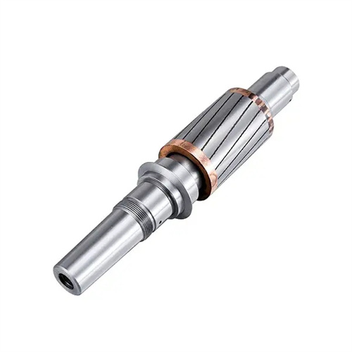
The clamping method for slender shafts should be selected based on the machining process and equipment type. The key is to ensure shaft rigidity and stability to prevent deformation during machining. Common clamping methods for machining slender shafts on lathes include single-clamp and double-center clamping, double-center clamping, and steady rest-assisted clamping. In single-clamp and double-center clamping, the chuck clamps one end of the shaft (with a clamping length of 1-1.5 times the shaft diameter) and supports the other end with a centering pin. To reduce radial forces exerted by the chuck on the shaft, the chuck jaws can be padded with copper or special soft jaws can be used. Double-center clamping is suitable for shafts with center holes at both ends. The front and rear centers support the shaft. This method offers high positioning accuracy, but lacks rigidity and requires a steady rest. Steady rest-assisted clamping is suitable for slender shafts with an aspect ratio greater than 50. The steady rest is fixed to the lathe bed and supports the shaft’s center section, improving its rigidity. A clearance of 0.05-0.1mm should be maintained between the steady rest’s support jaws and the shaft, and lubrication should be applied.
When machining slender shafts on a milling machine, the clamping method differs from that on a lathe. Commonly used clamping methods include vise clamping, V-shaped iron clamping, and special fixture clamping. The vise clamping method is suitable for machining the end of the shaft. One end of the shaft is clamped in a vise, while the other end is supported by a bracket. The jaws of the vise should be padded with copper sheeting to prevent damage to the shaft surface. The V-shaped iron clamping method is suitable for machining the outer diameter of the shaft. The shaft is placed on two V-shaped irons of equal height and clamped with a pressure plate. The angle of the V-shaped irons is generally 90° or 120°, depending on the shaft diameter. Special fixture clamping is suitable for mass production. The fixture can be designed according to the shaft structure and machining requirements. It offers the advantages of accurate positioning and fast clamping, effectively ensuring machining accuracy and efficiency.
The precautions taken when clamping slender shafts are crucial to ensuring processing quality. Before clamping, the surface of the shaft and the clamping tools must be cleaned to remove impurities such as oil, iron filings, and prevent impurities from affecting positioning accuracy. The clamping force should be uniform and moderate to avoid plastic deformation of the shaft due to excessive clamping force, or loosening of the shaft during processing due to insufficient clamping force. For slender shafts with extremely poor rigidity, a segmented clamping method can be used, that is, one end of the shaft is processed first, then the other end, and the middle part is fixed with auxiliary supports. The deformation of the shaft must be observed at all times during processing. If the shaft is found to bend or vibrate, the processing should be stopped immediately, and the clamping method should be readjusted or the shaft should be straightened. After processing is completed, the shaft should be placed horizontally on a dedicated bracket to prevent the shaft from bending and deforming due to its own weight. In addition, for slender shafts with high precision requirements, the ambient temperature must be controlled during clamping and processing to avoid thermal deformation of the shaft due to temperature changes.