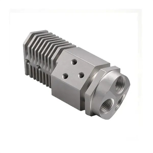
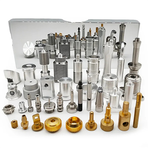
Whirlwind milling of elliptical cross-section rods
Whirlwind milling of elliptical cross-section rods is a highly efficient and precise specialized machining method suitable for mass production of slender rods with elliptical cross-sections. It has important applications in aerospace, automotive, and precision instrumentation. Compared to traditional turning or grinding, whirlwind milling, with its high-speed rotating tool system and unique feed method, significantly improves production efficiency while maintaining machining accuracy. The geometric characteristics of elliptical cross-section rods dictate their machining difficulty, requiring precise control of tool paths and cutting parameters to achieve accurate shaping of the elliptical profile .
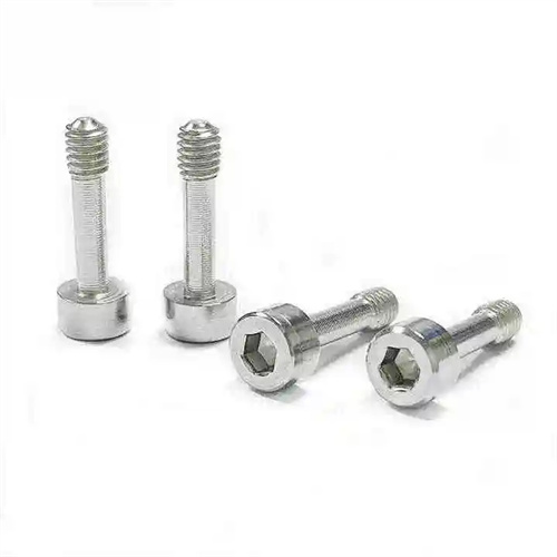
The key to whirling milling of elliptical cross-section rods lies in the design and adjustment of the tool system. The whirling milling cutterhead typically consists of multiple carbide tools, evenly distributed around the cutterhead’s circumference. The cutterhead axis forms a specific angle with the workpiece axis, which must be precisely calculated based on the major and minor axis dimensions of the ellipse and the helix angle. Tool geometry significantly influences machining quality. The rake angle is typically 10°-15° to reduce cutting forces and chip deformation; the clearance angle is 8°-12° to minimize friction between the tool and the workpiece surface. The lead angle is adjusted based on the curvature of the ellipse, decreasing at the major axis endpoints and increasing at the minor axis endpoints to ensure good contact between the tool cutting edge and the workpiece surface. The tool material should be a high-strength, high-wear-resistant carbide, such as a WC-Co alloy. For elliptical rods made of high-strength alloys, coated tools (such as TiAlN coatings) are also required to improve tool life and cutting efficiency.
The forming accuracy of the elliptical cross-sectional profile depends on the machine tool’s linkage control and trajectory planning. During cyclonic milling, the workpiece rotates about its own axis while the tool system feeds axially along the workpiece. The cutterhead also needs to perform additional swings or displacements based on the parameters of the ellipse, forming a composite motion trajectory. For CNC cyclonic milling machines, the mathematical equation of the ellipse (x²/a² + y²/b² = 1, where a and b are the major and minor semi-axes of the ellipse, respectively) must be converted into the tool’s motion trajectory through programming to ensure that the tool’s cutting edge is always tangent to the elliptical profile. Before machining, trajectory simulation is required to check whether the tool interferes with the workpiece, especially at the transition corners of the ellipse, where the tool radius must match the corner radius. To reduce contour errors, the machine tool’s positioning accuracy and repeatability must be controlled within 0.005mm, and the servo system’s response speed must also meet the requirements of high-speed cutting to avoid trajectory deviations caused by lag.
Optimizing cutting parameters is key to ensuring quality and efficiency when whirling milling elliptical cross-section rods. Due to the varying curvature of each point in the elliptical cross-section, the cutting speed varies with tool position, reaching its highest speed at the endpoints of the major axis and its lowest at the endpoints of the minor axis. Therefore, appropriate parameters must be selected based on the average cutting speed. The cutterhead speed is typically 3000-8000 rpm, the workpiece speed is 50-200 rpm, and the axial feed rate is 0.1-0.3 mm/r. The depth of cut should take into account the eccentricity of the ellipse. A depth of cut of 0.5-1 mm is recommended for rough milling, and 0.1-0.3 mm for fine milling to ensure a surface roughness of Ra 0.8-1.6 μm. For elliptical rods made of 45 steel, using carbide tools, the cutting speed can be controlled at 150-250 m/min. When machining difficult-to-machine materials such as stainless steel, the cutting speed should be reduced to 80-150 m/min, and the feed rate should be appropriately reduced to prevent tool overheating and wear.
Precision detection and error compensation of elliptical cross-section rods are important links in ensuring processing quality. Common detection methods include three-coordinate measuring machine detection and special measuring tool detection. The three-coordinate measuring machine can accurately measure the major axis, minor axis size, ellipticity and position of each section of the ellipse. When measuring, 5-8 sections should be evenly selected within the entire length of the rod, and more than 4 points should be measured in each section to ensure the representativeness of the detection results. The ellipticity error should be controlled within the range of 0.01-0.03mm. For high-precision rods, it should be controlled within 0.005mm. If the error is found to be out of tolerance during the detection, the cause needs to be analyzed and compensated, such as by adjusting the position compensation value of the tool to correct the dimensional deviation, or by modifying the machine tool parameters to adjust the trajectory accuracy. In addition, the straightness and circular runout of the rod need to be tested. The straightness error does not exceed 0.02mm/m, and the circular runout does not exceed 0.01mm to ensure the assembly performance of the rod.
Targeted process measures are required for whirling milling of elliptical cross-section rods made of different materials. When machining light metals such as aluminum alloys, due to the material’s good plasticity and strong thermal conductivity, tool sticking is prone to occur. Therefore, a tool with a larger rake angle and an emulsion (5%-8% concentration) should be used as a cutting fluid. Chip removal should also be enhanced to prevent chip accumulation and scratches on the machined surface. When machining high-strength steel (such as 40CrNiMoA), due to the material’s high hardness and toughness, the cutting forces and temperatures are high. Therefore, tough carbide tools (such as YW2) should be selected. Cutting speeds should be controlled at 100-150 m/min, feeds at 0.1-0.2 mm/r, and extreme pressure cutting oil should be used for cooling and lubrication to reduce tool wear. When processing titanium alloy, due to its high chemical activity, it is easy to bond with the tool material. Ceramic tools or CBN tools are required, with a cutting speed of 80-120m/min and a feed rate of 0.05-0.1mm/r. The cutting fluid must have good lubricity and oxidation resistance to avoid oxidation and discoloration of the titanium alloy surface.