Using a special fixture to turn an eccentric workpiece
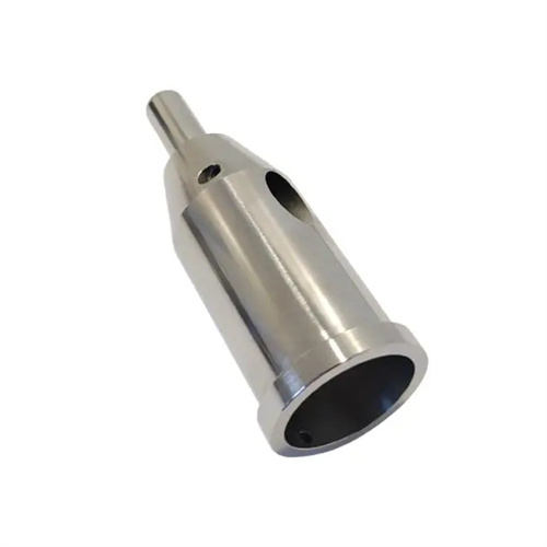
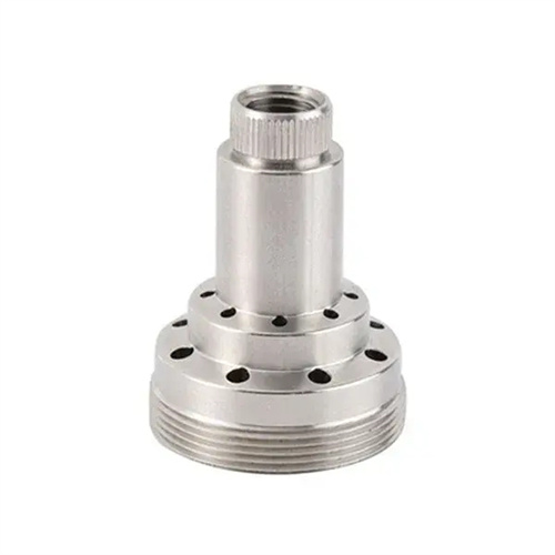
Eccentric workpieces are parts whose rotational axis and geometric axis do not coincide. These parts are widely used in mechanical transmissions, centrifugal mechanisms, and other fields, such as eccentric shafts, eccentric sleeves, and cams. Using specialized fixtures to turn eccentric workpieces effectively ensures machining accuracy and improves production efficiency, making them particularly suitable for mass production. Through precise positioning and reliable clamping, specialized fixtures maintain a stable eccentricity during machining, thereby ensuring the dimensional and positional accuracy of the eccentric portion. This is an effective solution to the machining challenges of eccentric workpieces.
The design of a special fixture is the key to turning eccentric workpieces. It must meet the requirements of accurate positioning, reliable clamping, and convenient operation. The positioning device is the core of the special fixture. Its function is to determine the correct position of the workpiece in the fixture and ensure that the eccentricity of the workpiece meets the design requirements. Common positioning methods include external circle positioning, internal hole positioning, and end face positioning. External circle positioning is suitable for eccentric workpieces based on the external circle of the workpiece. It is achieved through V-blocks or positioning sleeves. The angle of the V-block is generally 90° or 120°, and the positioning accuracy can reach 0.01-0.03mm; internal hole positioning is suitable for eccentric workpieces based on the inner hole of the workpiece. It is positioned using locating pins or spindles. The clearance between the locating pin and the inner hole should be controlled at 0.005-0.01mm to ensure positioning accuracy. The clamping device needs to provide sufficient clamping force to prevent the workpiece from loosening during processing, and avoid deformation of the workpiece caused by excessive clamping force. Commonly used clamping devices include bolt pressure plates, eccentric clamping mechanisms and pneumatic clamping mechanisms. Pneumatic clamping mechanisms are suitable for mass production, with fast clamping speed and uniform clamping force. The clamping force can be controlled by adjusting the air pressure (generally 0.3-0.5MPa).
The manufacturing accuracy of specialized fixtures directly impacts the machining precision of eccentric workpieces, requiring strict control of key dimensions and form and position tolerances. The parallelism error between the locating surfaces of the fixture’s locating elements and the fixture’s base should not exceed 0.005mm/100mm. The positional accuracy between locating elements (such as the symmetry of V-blocks and the coaxiality of locating pins) should be controlled within 0.003mm. The coaxiality error between the fixture’s guide elements (such as drill bushings and guide sleeves) and the locating elements should not exceed 0.005mm to ensure that the tool’s trajectory aligns with the positioning reference. The fixture body should possess sufficient rigidity and stability. It should be constructed of gray cast iron (such as HT300) or cast steel (such as ZG310-570) and undergo aging treatment to eliminate internal stresses and prevent deformation during use. The fixture’s assembly accuracy must also be strictly controlled. The clearances between components must meet design requirements, and moving parts (such as the clamping mechanism) must move freely without binding. The overall tolerance of the assembled fixture should not exceed 0.01mm.
The process steps for turning eccentric workpieces using a specialized fixture require scientific planning, including workpiece pretreatment, fixture installation and adjustment, trial cutting, and batch processing. During workpiece pretreatment, positioning reference surfaces, such as the outer diameter, inner hole, or end face, must be machined. The surface roughness of the reference surface should achieve Ra1.6μm or higher, and dimensional tolerances should be controlled within IT7-IT8 to ensure positioning accuracy. After the fixture is installed on the lathe spindle, it must be aligned so that the fixture’s positioning reference coincides with the lathe spindle axis. This alignment can be achieved using a dial indicator, measuring the radial runout of the fixture’s positioning surface. The error should be within 0.005mm. Trial cutting is crucial for ensuring batch processing quality. One or two workpieces are selected for trial cutting. After processing, the eccentricity, the dimensions of the eccentric portion, and the form and position tolerances are measured. If errors are found, the fixture’s positioning components or the tool position must be adjusted until the requirements are met. During batch processing, workpieces must be inspected regularly, with measurements taken every 10-20 pieces processed to promptly identify and resolve problems and ensure the stability of processing quality.
Controlling eccentricity is a key performance criterion for turning eccentric workpieces, requiring both process measures and measurement methods to ensure accuracy. There are various methods for measuring eccentricity. For small and medium-sized eccentric workpieces, direct measurement can be performed using a micrometer. The maximum and minimum diameters of the workpiece are measured separately. The eccentricity e = (maximum diameter – minimum diameter)/2. For eccentric workpieces requiring higher precision, an eccentricity gauge or a coordinate measuring machine can be used. An eccentricity gauge can measure up to 0.001mm and display the eccentricity value and direction in real time. During turning, eccentricity can be controlled by adjusting the position of the fixture’s locating elements. For example, a shim can be placed between the locating pin and the workpiece’s inner hole. The shim thickness is calculated based on the eccentricity deviation. For every 0.01mm increase in shim thickness, the eccentricity increases by 0.01mm. For mass-produced eccentric workpieces, a grouping and matching method can be employed. The workpiece and fixture locating elements are grouped according to dimensional tolerances to ensure eccentricity accuracy through appropriate matching.
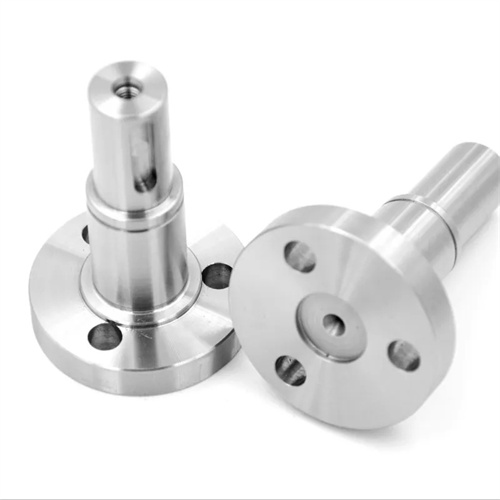
Targeted process measures are required when turning different types of eccentric workpieces (such as eccentric shafts, eccentric sleeves, and double-eccentric workpieces) using specialized fixtures. When turning eccentric shafts, if the eccentric portion is long, auxiliary supports are required on the fixture to prevent the workpiece from bending and deforming under the action of cutting forces. The contact pressure between the auxiliary supports and the workpiece should be moderate to avoid affecting positioning accuracy. When turning eccentric sleeves, due to the thin workpiece wall, clamping deformation is prone to occur. Therefore, a fixture with uniform radial clamping (such as a liquid plastic fixture) is required. This evenly distributes the clamping force and can control deformation to within 0.005mm. When turning a double-eccentric workpiece (with two parts of different eccentricity), a multi-station dedicated fixture is required, or the fixture’s indexing mechanism is used to achieve machining of the different eccentric parts. The indexing accuracy of the indexing mechanism should not exceed ±5″ to ensure the angular position accuracy between the two eccentric parts. In addition, the selection of cutting parameters should be determined based on the workpiece material and the size of the eccentricity. Generally, a lower cutting speed (80-150m/min), smaller feed rate (0.1-0.2mm/r) and cutting depth (0.5-1mm) are used to reduce cutting forces and vibration and ensure machining accuracy.