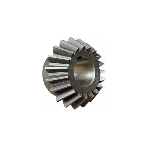
Milling rectangular tooth clutch
Milling rectangular tooth clutches is a key process for achieving synchronous rotation of two or more axes using milling machines. Due to their simple structure, high torque transmission, and smooth engagement, rectangular tooth clutches are widely used in machine tools, engineering machinery, and other fields. Processing quality depends on the accuracy of tooth profile, tooth parallelism, and side clearance. A tailored milling process plan is required based on the clutch structure (e.g., single-, double-, or multi-link) and material properties (e.g., 45 steel, cast iron).
The tooth profile of rectangular clutches dictates the selection and installation requirements of milling cutters, which are essential for ensuring tooth profile accuracy. The sides of rectangular teeth are parallel planes, and the tooth bottom is perpendicular to the axis. Therefore, an end mill or keyway milling cutter with sharp side cutting edges and straight cutting edges is required. The choice of tool material depends on the workpiece material. When machining medium-carbon steels such as 45 steel, a high-speed steel milling cutter (such as W18Cr4V) can be used. These are suitable for low-speed milling (15-30 m/min). After sharpening, the parallelism error between the two edges must not exceed 0.01 mm/100 mm. When machining cast iron or hardened steel, a carbide milling cutter (such as YT15) should be used. Cutting speeds can be increased to 50-80 m/min. A rake angle of 5°-10° and a clearance angle of 8°-12° are recommended to enhance blade strength. The diameter of the milling cutter must be matched with the width of the tooth groove. Generally, the diameter of the milling cutter is 0.1-0.2mm smaller than the width of the tooth groove to avoid overcutting on the tooth side. When installing the tool, it is necessary to align it with a dial indicator to ensure that the axis of the milling cutter is perpendicular to the feed direction of the worktable and the radial runout does not exceed 0.015mm.
The accuracy of the indexing mechanism directly affects the pitch uniformity of the rectangular tooth clutch and is a critical control link in the milling process. Common indexing methods include universal indexing heads, rotary tables, and dedicated fixtures. Universal indexing heads are the most widely used, offering an indexing accuracy of ±5″. Before indexing, the number of indexing handle revolutions must be calculated based on the number of clutch teeth using the formula n = 40/z (where z is the number of teeth). For non-divisible tooth numbers, a differential indexing method must be employed. The gear ratio between the indexing head spindle and the worktable must be adjusted using a pulley to ensure an indexing error of no more than ±3″. Care must be taken to eliminate internal clearance within the indexing head during indexing. This can be accomplished by rotating forward to shift the indexing head and retracting it in the reverse direction. The indexing head spindle must be locked after each indexing step to prevent displacement during milling. For multi-link clutches, the coaxiality of the tooth grooves of each link must also be ensured. The milling of all tooth grooves can be completed through one clamping, or the positioning pin and the reference hole can be used to ensure that the position error between each link does not exceed 0.02mm.
The milling process for rectangular tooth clutches is carried out in stages, with tooth profile accuracy and surface quality gradually improved by controlling cutting parameters. Rough milling involves removing most of the stock, using a lower cutting speed (10-20 m/min for high-speed steel milling cutters, 30-50 m/min for carbide milling cutters), a larger feed rate (0.1-0.2 mm/r), and a cutting depth (1-2 mm). The cutter axis must be aligned with the center of the workpiece, and a layered milling method is used. After each layer of cutting, the worktable is moved laterally by 0.5-1 mm until the tooth groove depth reaches 80% of the drawing requirements. Semi-finishing milling requires adjustment of cutting parameters, increasing the cutting speed by 10%-20%, reducing the feed rate to 0.05-0.1 mm/r, and controlling the cutting depth to 0.3-0.5 mm. At this point, the cutter position must be adjusted through trial cutting to ensure that the perpendicularity error between the tooth side and the workpiece axis does not exceed 0.01 mm/100 mm. During fine milling, a high-speed and low-feed method is used, with a cutting speed (25-35m/min for high-speed steel milling cutters and 60-80m/min for carbide milling cutters), a feed rate of 0.03-0.05mm/r, and a cutting depth of 0.1-0.2mm. After fine milling, the tooth surface roughness must reach Ra3.2μm or above, and the tooth thickness deviation must be controlled within the range of ±0.015mm.
Controlling the flatness and perpendicularity of the clutch mating surface is crucial for ensuring proper engagement, and this is achieved through both process measures and measurement methods. Before milling, the workpiece datum surface must be machined to ensure that the flatness of the positioning end face does not exceed 0.02mm/100mm, and the perpendicularity to the inner hole does not exceed 0.015mm/100mm. During positioning, the datum surface must be closely aligned with the worktable. A dial indicator can be used for alignment if necessary. If the error exceeds 0.01mm, copper pads should be used for leveling. During milling, the workpiece may deform slightly due to cutting forces. Therefore, a symmetrical cutting method should be employed during finish milling. This involves milling two symmetrical tooth grooves first, followed by machining the remaining tooth grooves. This minimizes deformation caused by unilateral forces. After machining, the mating surface should be checked for flatness using a flat plate and feeler gauge, and for perpendicularity using a square and dial indicator. Workpieces with excessive flatness can be corrected by grinding using an 800# grit silicon carbide grinding wheel with a grinding allowance of no more than 0.03mm.
Milling rectangular tooth clutches of different materials requires tailored process measures to ensure machining quality and efficiency. When machining plastic materials like 45 steel, the ribbon-like chips are prone to tangling around the milling cutter, necessitating the use of a chipbreaker cutter and enhanced cooling and lubrication of the cutting fluid. Use an emulsion (5%-8% concentration) with a flow rate of at least 10 L/min. Chips should be cleaned every 3-5 teeth to prevent scratching the machined surface. When machining brittle materials like cast iron, the powdery chips can easily enter the indexing mechanism, affecting accuracy. Therefore, a protective cover should be installed on the workbench, and the interior of the indexing head should be regularly purged with compressed air. Dry cutting or kerosene as a cutting fluid can be used to reduce dust generation. For hardened steel (hardness HRC40-50), ceramic milling cutters or CBN milling cutters should be used, the cutting speed should be controlled at 80-120m/min, the feed rate should be 0.02-0.04mm/r, and the reverse milling method should be used to avoid tool chipping. Stress relief treatment is required after milling to eliminate residual stress during processing.