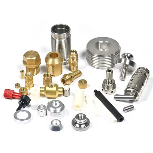
Indexable milling cutter
An indexable milling cutter is a milling cutter in which indexable inserts are fixed to the cutter body via a clamping mechanism. When the insert wears out, it can be directly indexed or replaced with a new one without sharpening. It offers advantages such as high machining efficiency, long tool life, and reduced tool change time. It is widely used in modern machining equipment such as CNC machine tools and machining centers, and is a vital tool for achieving efficient cutting. There are many types of indexable milling cutters, which can be categorized by application as face mills, end mills, and face and side mills; and by insert shape as triangular, square, and diamond shapes. The performance of an indexable milling cutter depends on factors such as the insert material, cutter body structure, clamping method, and geometric parameters. The proper selection and use of indexable milling cutters can significantly improve machining efficiency and quality while reducing production costs.
Indexable inserts are the core component of indexable milling cutters, and their material and type directly impact milling performance. Indexable insert materials primarily include carbide, ceramics, cubic boron nitride ( CBN ), and diamond. Carbide inserts are the most widely used and are categorized by application into P (for machining steel), M (for machining stainless steel and cast iron), and K (for machining cast iron and non-ferrous metals). For example, P10 is suitable for high-speed finish machining of steel, while K10 is suitable for finish machining of cast iron. Ceramic inserts (such as Al₂O₃ -based and Si₃N₄ -based) offer high hardness and excellent wear resistance, making them suitable for machining difficult-to-machine materials such as high-strength steel and cast iron. However, they are also brittle and therefore suitable for continuous cutting. CBN inserts are suitable for machining superhard materials such as hardened steel and high-temperature alloys, while diamond inserts are suitable for machining non-ferrous metals and non-metallic materials, offering high precision and excellent surface quality. Indexable insert models are regulated by national standards. For example, the triangular insert is designated TNMG160408, where “TNMG” indicates the insert’s shape, back angle, precision grade, and mounting method, and “160408” refers to the insert’s side length, thickness, and nose radius. Insert selection should be based on the material being machined, cutting conditions, and processing requirements. For example, K-type carbide inserts should be used for machining cast iron, while P-type or ceramic inserts should be used for machining high-strength steel.
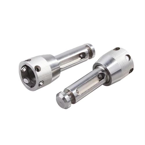
The cutter body structure and clamping method are crucial components of indexable milling cutters, directly impacting their rigidity, precision, and safety. The cutter body is typically made of 40Cr or 45 steel, tempered to a hardness of 220-250HB, providing sufficient strength and toughness. The cutter body is equipped with insert pockets, a clamping mechanism, and chip flutes. The shape and size of the chip flutes must be designed based on the cutting load and workpiece material to ensure smooth chip removal and prevent chip blockage. Clamping methods include eccentric, lever, wedge, and screw types. Eccentric clamping offers a simple structure and ease of operation, making it suitable for light-duty milling. Lever clamping provides superior rigidity and reliability, making it suitable for heavy-duty milling. Wedge clamping offers high positioning accuracy, making it suitable for high-precision milling. Screw clamping is suitable for smaller inserts. The clamping mechanism must ensure that the insert does not loosen or shift during cutting, and that the insert and the cutter body’s positioning surface are in close contact, with a positioning accuracy of ≤0.01mm. The dynamic balance performance of the cutter body is crucial for high-speed milling. When the milling speed exceeds 3000r/min, the cutter body needs to be dynamically balanced. The imbalance should be controlled within G2.5 to avoid vibration, which affects the processing quality and tool life.
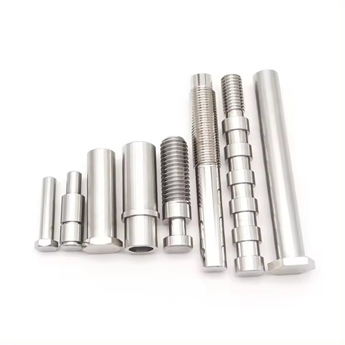
The geometric parameters of indexable milling cutters include the rake angle, clearance angle, lead angle, secondary angle, and nose radius. These parameters must be selected based on the material being machined and the machining requirements. The rake angle influences cutting force and chip formation. When machining plastic materials (such as steel), the rake angle should be 10°-15°; when machining brittle materials (such as cast iron), the rake angle should be 0°-5°. When machining difficult-to-machine materials, a negative rake angle (-5°-0°) should be used to enhance cutting edge strength. A clearance angle of 5°-10° ensures sufficient clearance between the tool and the workpiece, reducing friction. The lead angle influences cutting force distribution and tool life. Commonly used lead angles are 45°, 60°, and 90°. A 45° lead angle milling cutter provides uniform cutting force distribution and is suitable for milling flat surfaces; a 90° lead angle milling cutter is suitable for milling stepped surfaces and right angles. A secondary angle of 5°-10° reduces residual area on the machined surface and improves surface quality. The tool tip radius should be between 0.4 and 1.6 mm. A larger tip radius increases tool tip strength and reduces vibration, but also increases cutting force and surface roughness. For example, face milling cutters typically have a 45° entering angle, a 10° rake angle, a 6° clearance angle, and a 0.8 mm tip radius, making them suitable for milling flat surfaces in steel and cast iron.
The selection and use of indexable milling cutters require adherence to certain principles to maximize their performance. Choose the cutter type based on the type of work being done: a face milling cutter for flat surfaces, a side and face milling cutter for grooves, and an end mill for contours. Choose the insert material and geometry based on the material being worked on: for example, diamond inserts with a rake angle of 15°-20° are recommended for machining aluminum alloys; CBN inserts with a rake angle of -5°-0° are recommended for machining hardened steel. Choose the cutter size and cutting parameters based on the machine tool’s capabilities: CNC machine tools and machining centers offer superior rigidity and power, allowing for larger diameter cutters and higher cutting parameters. Conventional milling machines require lower cutting speeds and feeds. Regularly check insert wear during use. When flank wear reaches 0.3-0.5mm, index or replace the insert promptly to prevent degradation in machining quality due to blade wear. When installing the insert, ensure the blade and cutter body’s positioning surfaces are clean and the clamping force is even to prevent blade deformation. In addition, it is necessary to choose the cutting fluid reasonably. When processing steel and cast iron, use extreme pressure emulsion, and when processing aluminum alloy, use kerosene or emulsion to reduce cutting temperature, reduce tool wear and improve surface quality.