Causes of machining errors and ways to improve machining accuracy
Machining error refers to the deviation between the actual geometric parameters (size, shape, and position) of a machined part and its ideal geometric parameters. It is an unavoidable phenomenon in mechanical processing, but excessive errors can affect the part’s assembly performance and functionality. Analyzing the causes of machining error and taking targeted measures to improve machining accuracy are important topics in mechanical manufacturing. The causes of machining error can be summarized as geometric errors in the process system, deformation errors due to stress, thermal deformation errors, errors caused by internal stress in the workpiece, and measurement errors. Improving machining accuracy can be achieved through reducing, compensating for, offsetting, transferring, and averaging the original errors. The appropriate method should be selected based on specific production conditions.
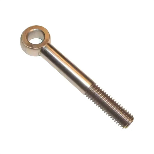
Geometric errors in the process system are one of the main sources of machining errors. These errors include manufacturing errors and wear errors in the machine tool, cutting tools, and fixtures. Machine tool geometric errors significantly impact machining accuracy. For example, radial runout of a lathe spindle can cause roundness errors in the workpiece’s outer diameter. Straightness errors in lathe guideways can cause cylindricity errors in the workpiece. Parallelism errors between the spindle and guideway can cause flatness errors in the workpiece’s end faces. For example, if the spindle’s radial runout is 0.01mm, the roundness error of the outer diameter of the machined shaft part will be at least 0.01mm. Tool geometric errors include both manufacturing errors and wear errors. For example, errors in the drill’s top angle can lead to an enlarged hole diameter and skewed hole axis, while wear on a turning tool can cause the workpiece diameter to gradually increase. Fixture geometric errors primarily manifest in the accuracy of the positioning, clamping, and guiding elements. For example, errors in the perpendicularity of the drill sleeve’s axis to the positioning plane can lead to positional errors in the drilled hole. In order to reduce geometric errors, high-precision machine tools, cutting tools and fixtures must be selected, and regular inspection and maintenance must be carried out to control the wear within the allowable range (for example, the wear of the flank of the turning tool generally does not exceed 0.3mm).
Deformation of the process system under stress is another significant cause of machining errors. External forces such as cutting force, clamping force, and gravity cause elastic deformation of the process system, disrupting the correct relative position between the tool and workpiece, leading to machining errors. For example, when turning a slender shaft, the workpiece bends under the action of cutting forces, resulting in a “drum” shape (larger diameter in the middle and smaller diameter at the ends). When milling thin plate parts, the workpiece warps under the action of clamping forces. After machining, loosening the fixture allows the deformation to recover, resulting in part flatness deviations. The stiffness of the process system is a key factor influencing deformation under stress; lower stiffness results in greater deformation. To improve process system stiffness, the following measures can be taken: increasing the stiffness of machine tool components, such as adding ribs to the lathe bed guideways; increasing workpiece stiffness, such as using a steady rest or steady rest to support the slender shaft; optimizing tool structure, such as using a turning tool with a large entering angle to reduce radial cutting forces; and selecting appropriate clamping methods, such as multi-point clamping or elastic clamping to reduce workpiece deformation. In addition, deformation can be reduced by reducing cutting force (such as reducing feed rate and cutting depth). For example, when turning slender shafts, reducing the feed rate from 0.3mm/r to 0.1mm/r can reduce the radial cutting force by more than 50% and significantly reduce the deformation.
Thermal deformation error is a machining error caused by thermal expansion or contraction of various components of the process system during machining due to factors such as cutting heat, frictional heat, and ambient temperature changes. In precision machining, thermal deformation error is often the main factor affecting machining accuracy, accounting for 40%-70% of the total error. For example, during grinding, the friction between the grinding wheel and the workpiece generates a large amount of heat, causing the workpiece temperature to rise. If the workpiece is not cooled in time, dimensional errors will occur due to thermal expansion. After cooling, the size will shrink, resulting in undersized parts. In precision lathe machining, the temperature rise of the spindle box can cause the spindle axis to rise and tilt, resulting in machining errors. In order to reduce thermal deformation errors, effective temperature control measures need to be taken: control the generation and conduction of cutting heat, such as using high-efficiency cooling lubricants (such as emulsions, cutting oils) to remove the cutting heat through high-pressure injection; reduce the internal heat source of the machine tool, such as forced cooling of heat-generating components such as motors and bearings; control the ambient temperature, such as using constant temperature measures in precision machining workshops (temperature controlled at 20±0.5℃) to avoid excessive temperature fluctuations; use thermal error compensation technology to measure the thermal deformation in real time through sensors, and the CNC system automatically compensates the position of the tool or workpiece.
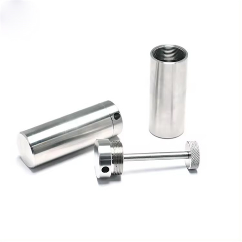
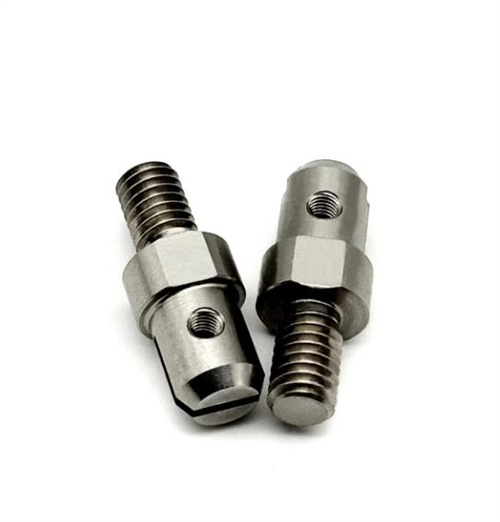
Errors caused by internal stress in a workpiece refer to residual stress generated during the roughcast manufacturing, heat treatment, and cutting processes. These residual stresses gradually release during machining, leading to deformation and thus machining errors. For example, during the solidification process of a casting, internal stresses are generated due to the varying cooling rates of different parts. After rough machining, these internal stresses redistribute and cause bending or warping in the workpiece. After quenching, structural stresses build up within the workpiece. Without aging treatment, dimensional and shape errors can occur after machining. To reduce errors caused by internal stresses, aging treatment is required before machining to eliminate residual stresses. Common aging methods include natural aging (exposing the workpiece to a natural environment for 3-6 months), artificial aging (heating the workpiece to 100-200°C for 2-4 hours ), and vibration aging (releasing internal stresses through vibration). For parts requiring high precision, a “rough machining-aging treatment-finishing” process can be used to fully release internal stresses after rough machining and minimize deformation after finishing. For example, when processing precision screws, they need to undergo multiple aging treatments, and aging is performed after each processing to ensure the dimensional stability of the screws.
In addition to reducing the above-mentioned original errors, other ways to improve machining accuracy include error compensation, error transfer, error averaging, and other advanced methods. The error compensation method artificially introduces an additional error to offset or reduce the original error. For example, when scraping on a machine tool guide rail, the guide rail is deliberately made to produce a certain reverse error to compensate for the deformation error when the worktable moves. On a CNC machine tool, the positioning error of each axis is measured by a laser interferometer, and the error value is input into the CNC system, and the system automatically compensates during processing. The error transfer method transfers the original error to a direction or position that does not affect the machining accuracy. For example, when boring on a boring machine, the radial runout error of the machine tool spindle is transferred to the axial direction. By using a floating boring tool, the tool and the spindle are floatingly connected, thereby avoiding the influence of the spindle error on the hole accuracy. Error averaging utilizes the equalizing effect of the workpiece or tool to offset errors. For example, in grinding, the relative motion of the workpiece and the grinding tool gradually reduces errors and improves surface accuracy. In gear machining, the meshing motion of the gear and shaving cutter is used to evenly distribute tooth surface errors and improve tooth profile accuracy. Furthermore, comprehensive improvements in machining accuracy can be achieved by improving measurement accuracy, strengthening quality control, and optimizing machining parameters to meet part design requirements.