Machining thin-walled workpieces
Machining thin-walled workpieces is one of the most challenging aspects of machining. Due to their thin walls and poor rigidity, thin-walled workpieces are easily deformed during the turning process by factors such as cutting forces, clamping forces, and cutting heat. This makes it difficult to guarantee the workpiece’s dimensional accuracy, shape precision, and surface quality. Thin-walled workpieces are widely used in aerospace, automotive manufacturing, precision instruments, and other fields, such as engine cylinder liners, hydraulic cylinder barrels, and instrument housings. The machining quality of these workpieces directly affects the performance and lifespan of the entire machine. Therefore, studying and mastering the key technical points of turning thin-walled workpieces and implementing effective anti-deformation measures are of great significance for improving the machining quality of thin-walled workpieces.
Proper selection of tool material and geometry is crucial for minimizing deformation during turning of thin-walled workpieces. Thin-walled workpieces have low rigidity and are prone to vibration during cutting. Therefore, cutting tools should be sharp and wear-resistant to minimize cutting forces and vibration. Carbide or ceramic cutting tools are preferred, as these materials offer high hardness and wear resistance, enabling high cutting speeds and reducing friction and compression with the workpiece. Tool geometry should be optimized. The rake angle should be appropriately increased (generally 15°-25°) to minimize deformation and cutting forces. The clearance angle should also be appropriately increased (generally 8°-12°) to reduce friction between the tool’s flank and the machined workpiece surface. The lead angle should be large (generally 75°-90°) to reduce radial cutting forces and prevent workpiece bending. For example, when turning thin-walled aluminum alloy workpieces, using larger rake and clearance angles can significantly reduce cutting forces and prevent workpiece deformation due to excessive forces. In addition, the tool tip radius should be small (generally 0.2-0.5mm) to reduce extrusion and friction during cutting and reduce surface roughness.
Optimizing cutting parameters is crucial for controlling deformation during turning of thin-walled workpieces. The selection of cutting speed, feed rate, and depth of cut directly impacts cutting forces, cutting heat, and machined surface quality. When turning thin-walled workpieces, a higher cutting speed should be used to reduce cutting forces and heat. A higher cutting speed allows the cutting edge to penetrate the workpiece more quickly, shortening the contact time between the tool and the workpiece, thereby reducing the impact of cutting forces on the workpiece. For example, when turning thin-walled steel workpieces, the cutting speed can be controlled at 100-150 m/min; when turning thin-walled aluminum alloy workpieces, the cutting speed can be increased to 200-300 m/min. The feed rate should be kept low (generally 0.05-0.15 mm/r) to reduce cutting forces and surface roughness. However, a feed rate that is too low will increase cutting time and reduce machining efficiency. Therefore, it is important to select an appropriate feed rate while ensuring machining quality. The cutting depth should be determined according to the processing stage. A larger cutting depth (generally 1-3mm) can be selected for rough processing to quickly remove excess material; a smaller cutting depth (generally 0.1-0.5mm) should be used for fine processing to reduce cutting force and work hardening to ensure processing accuracy.
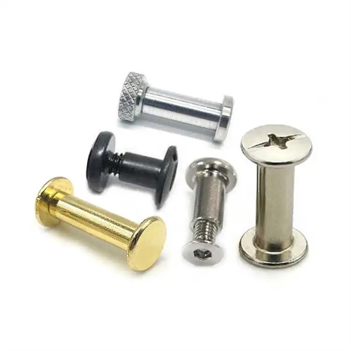
Adopting a suitable clamping method is an effective way to prevent deformation during turning of thin-walled workpieces. Traditional direct clamping with three-jaw or four-jaw chucks can easily cause radial deformation in thin-walled workpieces, necessitating specialized clamping methods. For thin-walled sleeve-like workpieces, axial clamping can be employed, using end-face positioning to clamp the workpiece and reduce the impact of radial clamping forces on the workpiece. For example, a mandrel and a pressure plate can be used for clamping. The mandrel and the workpiece inner bore are fitted with a transition fit. The pressure plate applies axial pressure to the workpiece against the fixture, distributing the clamping force axially and preventing radial deformation. For thin-walled disc-like workpieces, vacuum or electromagnetic chucks can be used for clamping. These utilize atmospheric pressure or electromagnetic force to evenly hold the workpiece against the worktable, achieving zero-clamping force and effectively preventing deformation. Furthermore, specialized clamps, such as soft jaws or sector-shaped jaws, can be used to increase the clamping area and evenly distribute the clamping force, preventing deformation caused by excessive localized forces. During the clamping process, the clamping force should be controlled and, if necessary, a force measuring device can be used for monitoring to ensure that the clamping is reliable and does not cause deformation.
Effective cooling and lubrication measures can lower cutting temperatures, reduce tool wear, and prevent thermal deformation of thin-walled workpieces, which can affect machining accuracy. Thin-walled workpieces have thin walls and low heat capacity, making them susceptible to thermal deformation during cutting due to cutting heat. Therefore, adequate cooling and lubrication are essential. Cooling lubricants should be extreme-pressure emulsions or cutting oils with excellent cooling, lubricity, and penetrating properties to reduce friction between the tool and the workpiece, and between the tool and the chips, thereby lowering cutting temperatures. High-pressure jet cooling should be used, spraying the cooling lubricant directly onto the cutting area to ensure adequate cooling. For thin-walled workpieces requiring high precision, oil mist lubrication or cryogenic cooling can further enhance cooling effectiveness. For example, when turning precision thin-walled bearing sleeves, oil mist lubrication creates a uniform oil film on the cutting surface, reducing friction and heat generation while preventing contamination of the cooling lubricant on the workpiece. Furthermore, chips should be removed promptly to prevent accumulation on the workpiece surface, which can cause localized overheating and deformation.
Proper machining technology also plays a significant role in controlling deformation during turning of thin-walled workpieces. The turning of thin-walled workpieces should adhere to the principles of “roughing first, finishing second, interior first, exterior second, and symmetrical machining” to reduce machining stress and deformation. During roughing, most of the stock should be removed to relieve internal stress and prepare for finishing. After roughing, the workpiece should be aged to eliminate machining stress and prevent deformation during subsequent machining. During finishing, smaller cutting parameters should be used to gradually improve workpiece accuracy, and the final depth of cut should be minimized to ensure surface quality. For thin-walled workpieces with high requirements for internal and external circumferential coaxiality, machining both the internal and external circumferences should be completed in a single clamping to avoid positioning errors caused by multiple clampings. For example, when turning thin-walled cylinder liners, the inner bore can be machined first, followed by the outer diameter, using the inner bore as a reference, to ensure coaxiality. Furthermore, during turning, the workpiece cantilever length should be minimized to increase workpiece rigidity. If necessary, a steady rest or steady rest can be used for auxiliary support to prevent bending and deformation caused by cutting forces. By rationally arranging the processing technology, the turning deformation of thin-walled workpieces can be effectively controlled to ensure the processing quality.