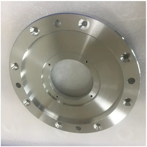
Machining eccentric workpieces
An eccentric workpiece is one whose outer diameter or inner bore axis does not coincide with the reference axis, resulting in a certain eccentricity. These parts are widely used in mechanical transmission, centrifugal mechanisms, and other fields, such as eccentric shafts and eccentric sleeves. The key to turning eccentric workpieces lies in ensuring the accuracy of the eccentricity and the workpiece’s shape. Because eccentric workpieces generate significant centrifugal force during rotation, they can easily cause vibration and deformation, potentially compromising machining safety. Therefore, turning eccentric workpieces is challenging. Before turning an eccentric workpiece, it is necessary to select the appropriate clamping method and machining method based on the workpiece’s structural characteristics, eccentricity, and precision requirements to ensure machining quality and production safety.
When turning eccentric workpieces, the choice of clamping method is crucial, directly affecting the accuracy of the eccentricity and the stability of the machining process. Common clamping methods include three-jaw chuck clamping, four-jaw chuck clamping, two-center clamping, and special fixture clamping. The three-jaw chuck clamping method is suitable for eccentric workpieces with small eccentricity (generally less than 5mm) and low precision requirements. By inserting a shim of a certain thickness into one of the jaws of the three-jaw chuck, the workpiece axis is offset from the spindle axis, thus achieving eccentric machining. The shim thickness can be calculated based on the eccentricity, generally about 1.5 times the eccentricity, but precise adjustment requires trial cutting. The four-jaw chuck clamping method is suitable for eccentric workpieces with larger eccentricity and higher precision requirements. By adjusting the position of each of the four jaws, the eccentric axis of the workpiece is aligned with the spindle axis. A dial indicator is used during clamping to ensure accurate eccentricity. The two-center clamping method is suitable for eccentric shaft workpieces with relatively large length-to-diameter ratios. By drilling eccentric center holes on both end faces of the workpiece and using center positioning and clamping, the stability of the workpiece during processing and the accuracy of the eccentricity can be guaranteed. It is especially suitable for mass production.
Tool selection for turning eccentric workpieces requires consideration of factors such as the workpiece material, machining accuracy, and cutting conditions. Because eccentric workpieces generate significant centrifugal forces and vibration during machining, the tool must possess high strength and rigidity to prevent edge chipping. For eccentric steel workpieces, carbide tools such as YT15 and YG8 are suitable. These tools offer high hardness, excellent wear resistance, and can withstand high cutting forces. For eccentric workpieces made of brittle materials such as cast iron, YG carbide tools can be used to reduce tool wear. Tool geometry should also be optimized. Generally, the rake angle should be 5°-15°, the relief angle 6°-10°, and the lead angle 75°-90° to reduce cutting forces and vibration. Furthermore, the tool nose radius should be small, typically 0.2-0.5mm, to reduce extrusion and friction during cutting and improve surface quality. A larger nose radius can be used for roughing to enhance tool strength, while a smaller nose radius should be used for finishing to ensure surface roughness requirements.
Proper selection of cutting parameters significantly impacts the machining quality and efficiency of turning eccentric workpieces. Because eccentric workpieces generate significant centrifugal forces during rotation, cutting speeds should be kept to a minimum to avoid exacerbating vibration and tool wear. For eccentric steel workpieces, the cutting speed is generally 50-80 m/min for roughing and 80-120 m/min for finishing. For eccentric cast iron workpieces, the cutting speed can be reduced to 40-60 m/min for roughing and 60-100 m/min for finishing. The feed rate should be determined based on the machining stage and surface quality requirements. A higher feed rate (0.2-0.3 mm/r) can be used for roughing to quickly remove excess material, while a lower feed rate (0.1-0.15 mm/r) should be used for finishing to improve surface quality. The depth of cut should also take into account the workpiece’s eccentricity and allowance. Suitable values are 1-3 mm for roughing and 0.1-0.5 mm for finishing. During the turning process, the cutting parameters should be adjusted in time according to the vibration of the workpiece to avoid affecting the processing accuracy and surface quality due to excessive vibration.
When turning eccentric workpieces, the following key points should be noted: First, the workpiece should be scribed before machining to determine the position and size of the eccentric part, providing a basis for clamping and alignment; second, aging treatment should be performed after rough machining to eliminate machining stress and avoid deformation during subsequent machining; third, for workpieces with multiple eccentricities, the machining sequence should be arranged reasonably, first machining the reference part, and then machining the other eccentric parts using the reference part as the positioning reference to ensure the position accuracy between the eccentric parts; fourth, during the machining process, a dial indicator or other measuring tool should be used to measure the eccentricity in real time, and the clamping position should be adjusted in time to ensure that the eccentricity accuracy meets the requirements; fifth, for large eccentric workpieces, counterweights can be used to balance centrifugal force, reduce vibration, and ensure machining safety. By mastering these key points, the turning quality and efficiency of eccentric workpieces can be effectively improved.